Assembling Serial IDC to DB9 Cable
Assembling Serial Adapter Cable
In order to connect the RS-232 from the Iris or Ixora carrier boards to a DB9 connector, you must assemble a 10-pin IDC to DB9 adapter. The following steps will guide you through assembling your adapter cable.
You may buy one adapter, paying attention to the standard - usually called DTK or Intel standard. It is available in the Carrier Board Accessory Kit and from many electronic components suppliers, e.g. here.
Bill of Materials
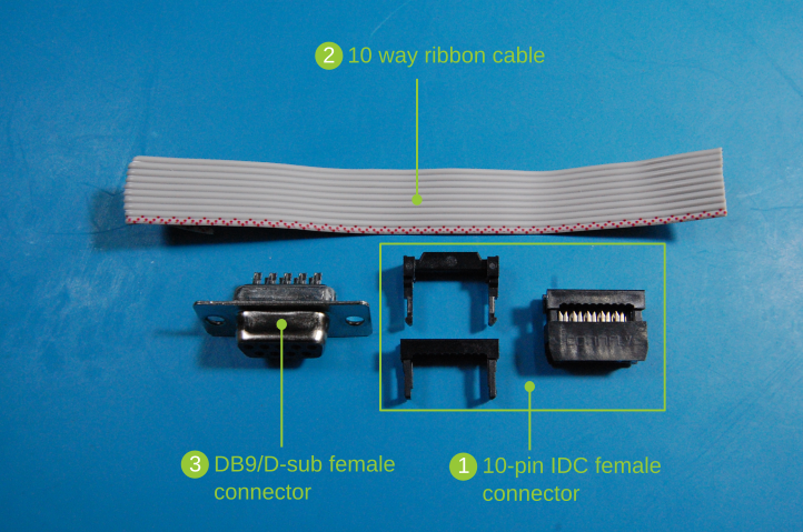
You will need:
- 10-pin IDC female connector
- 10 way ribbon cable (>10cm)
- DB9/D-sub female connector (preferably a 10-pin IDC to 9-pin D-sub male connector)
- Solder wire and soldering iron, depending on your DB9/D-sub connector
you may use another cable type and length, depending on your preference
The image below presents the bill of materials required for the adapter:
Verify the UART pinout
Verify the pinout of the carrier board pin header and the serial DB9 connector.
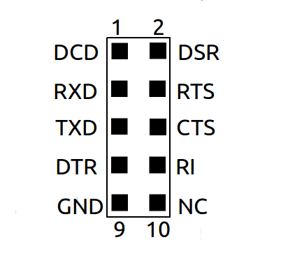
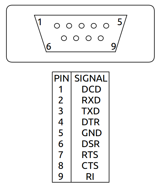
The TX from the IDC header must be connected to the RX from the DB9 connector. The RX from the IDC header must be connected to the TX from the DB9 connector.
Crimp the IDC connector
Crimp the ribbon cable to the IDC connector.
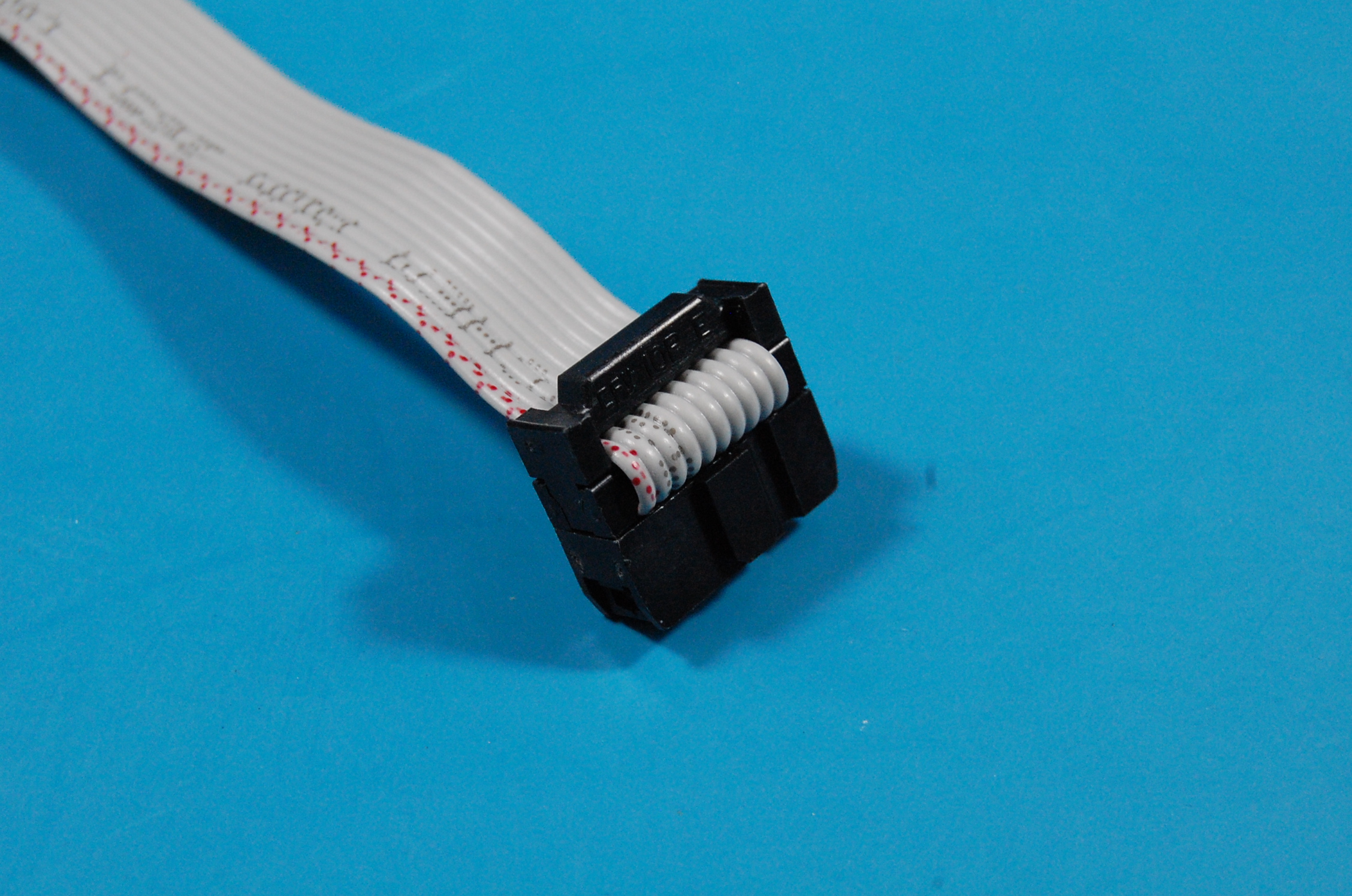
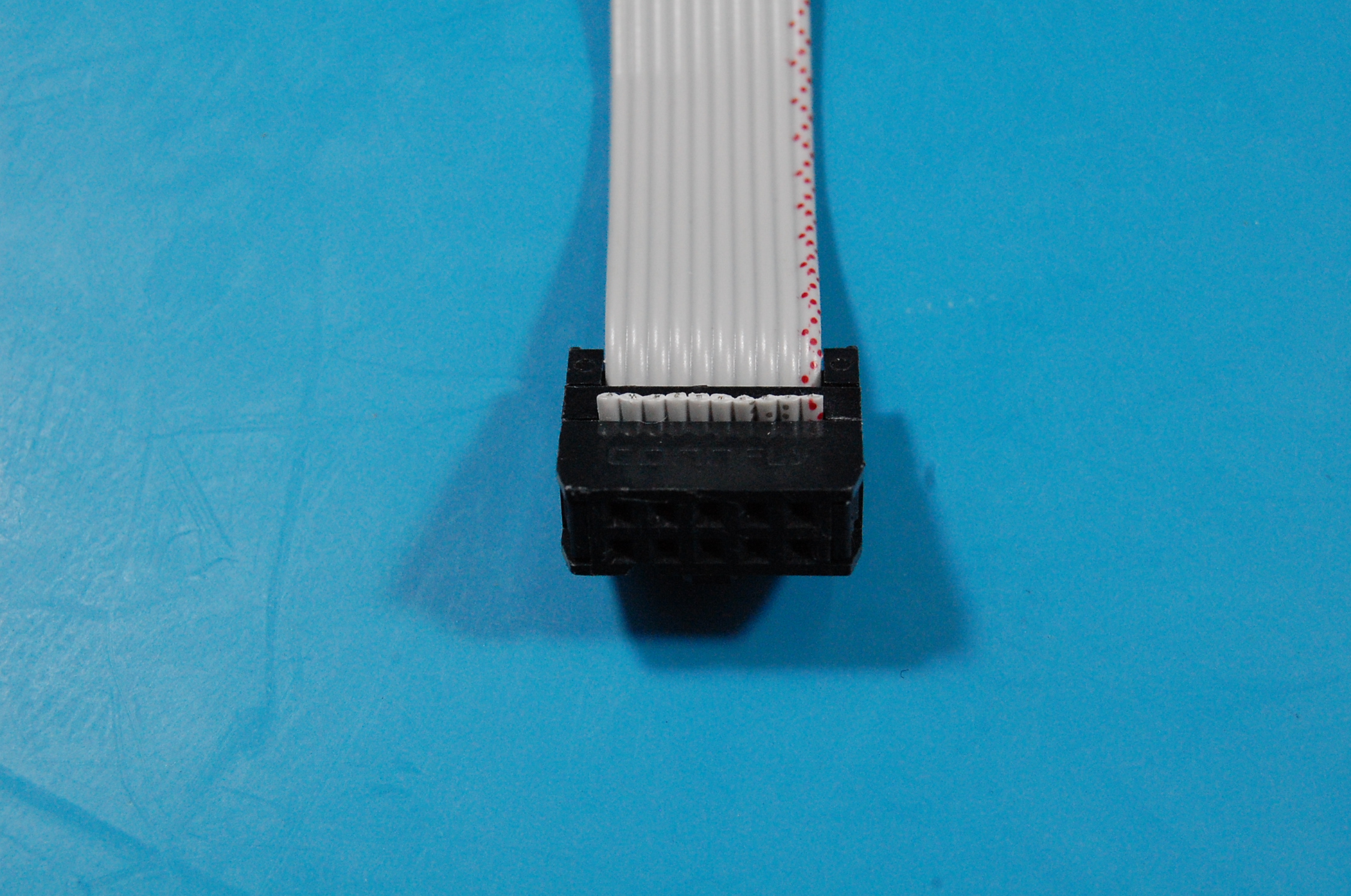
It might be interesting to define a pattern in this step such as always having the ribbon cable to the left of the even pins of the connector, since the carrier board does not have an IDC header to prevent inverted polarity, but instead only a pin header.
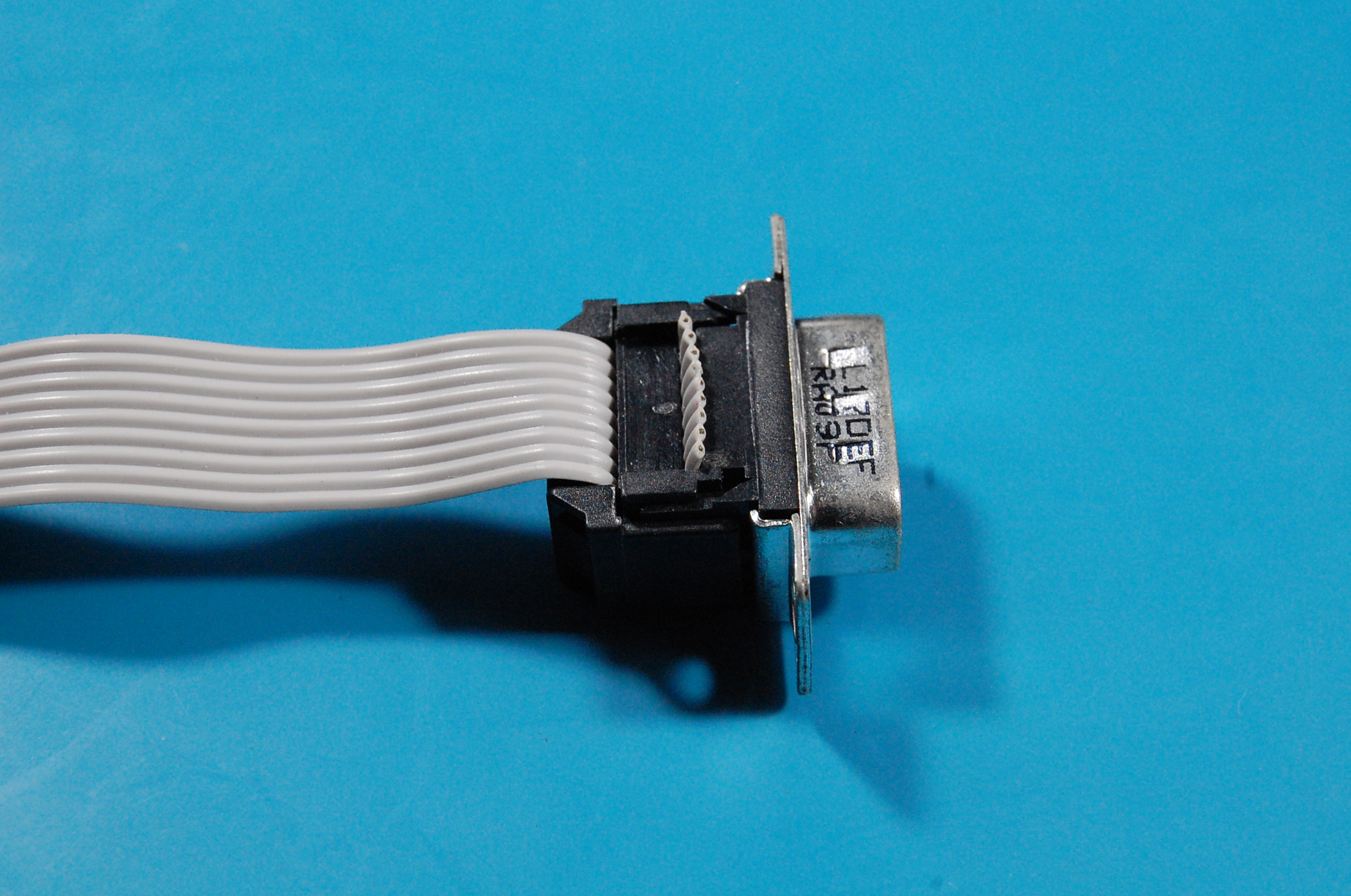
Crimp the DB9 connector
If you have an IDC to DB9 connector, also crimp it paying attention to the pins correspondence.
Beware that you may either:
- Invert the Tx and Rx pins, or;
- Use a null modem cable/adapter, or;
- Use a serial to USB adapter that accepts configurable Tx and Rx pins.
if nothing appears on the serial terminal emulator, consider the hypothesis that Tx and Rx pins may be inverted.
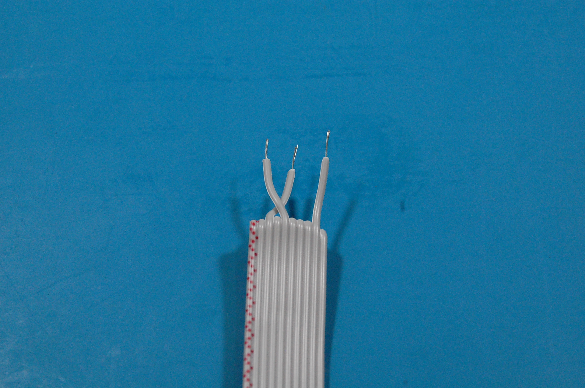
Strip the ribbon cable
If your DB9 connector needs to be soldered, do it only for the Tx, Rx and ground pins. Strip the ribbon cable:
customers reported issues if all pins are connected, therefore we recommend that you only solder the Tx, Rx and GND as described in the upcoming instructions.
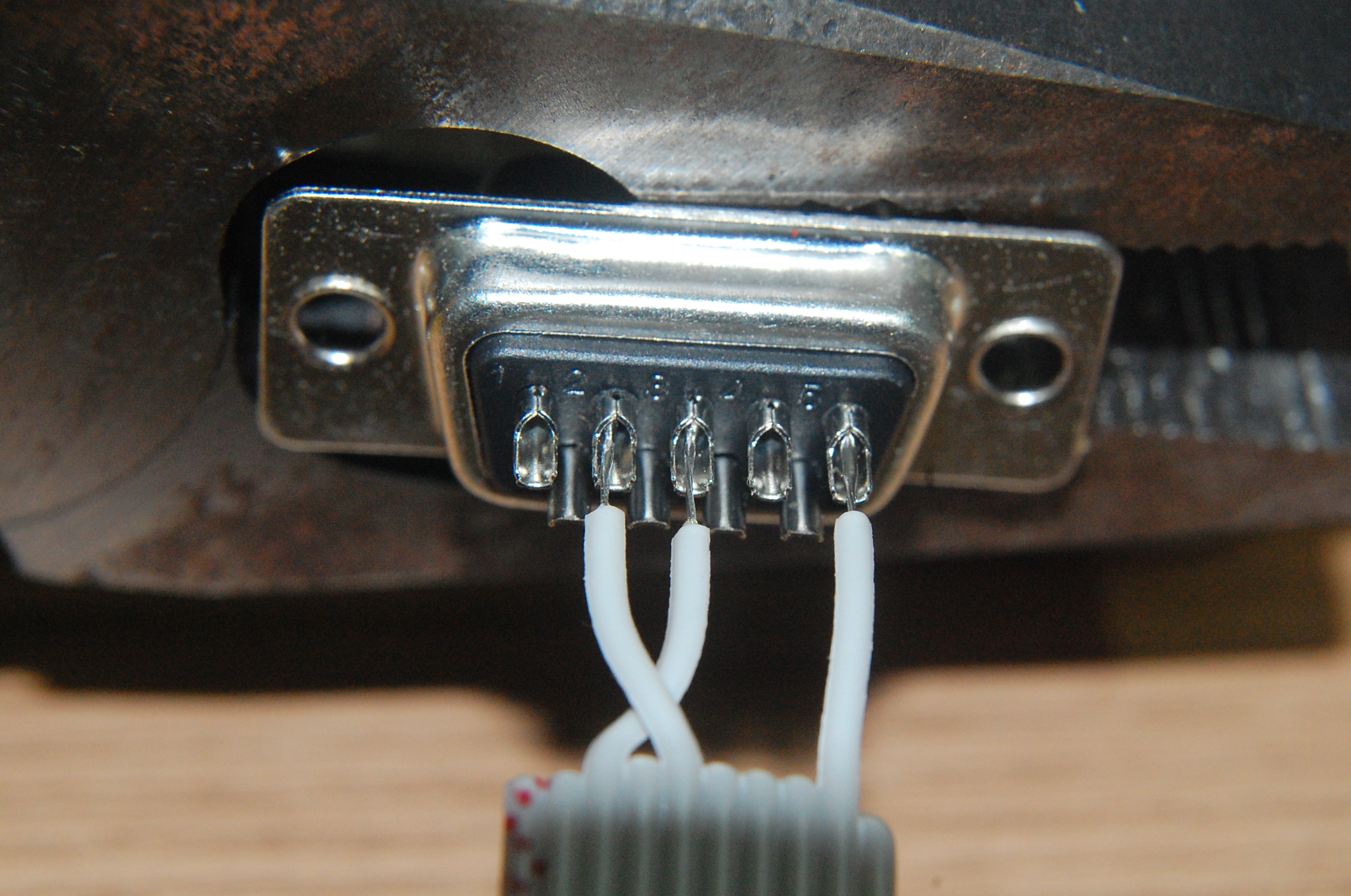
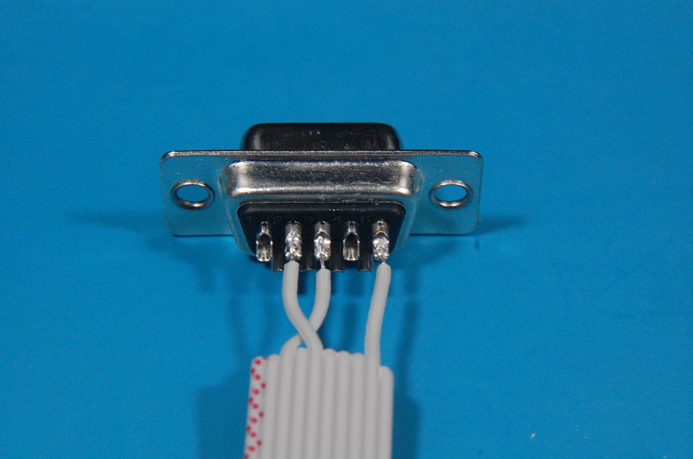
Solder the DB9 connector
Solder the ribbon cable into the DB9 connector:
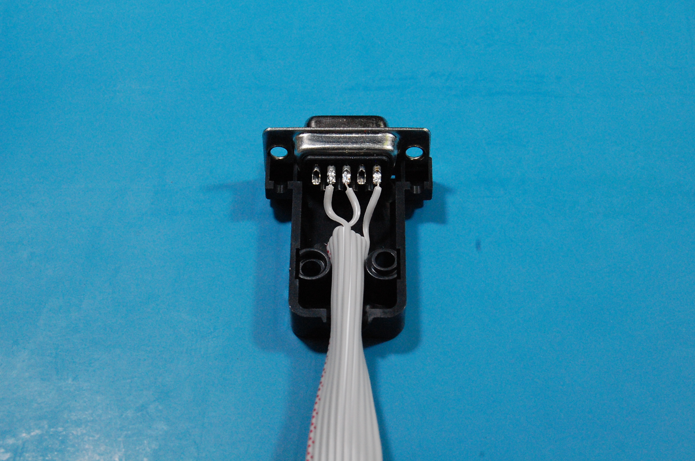
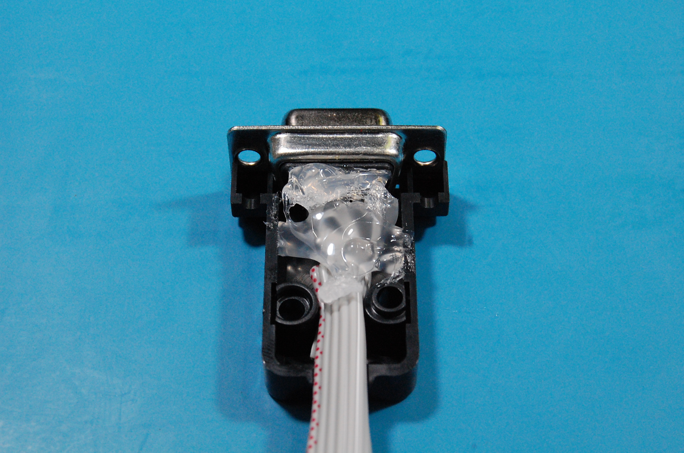
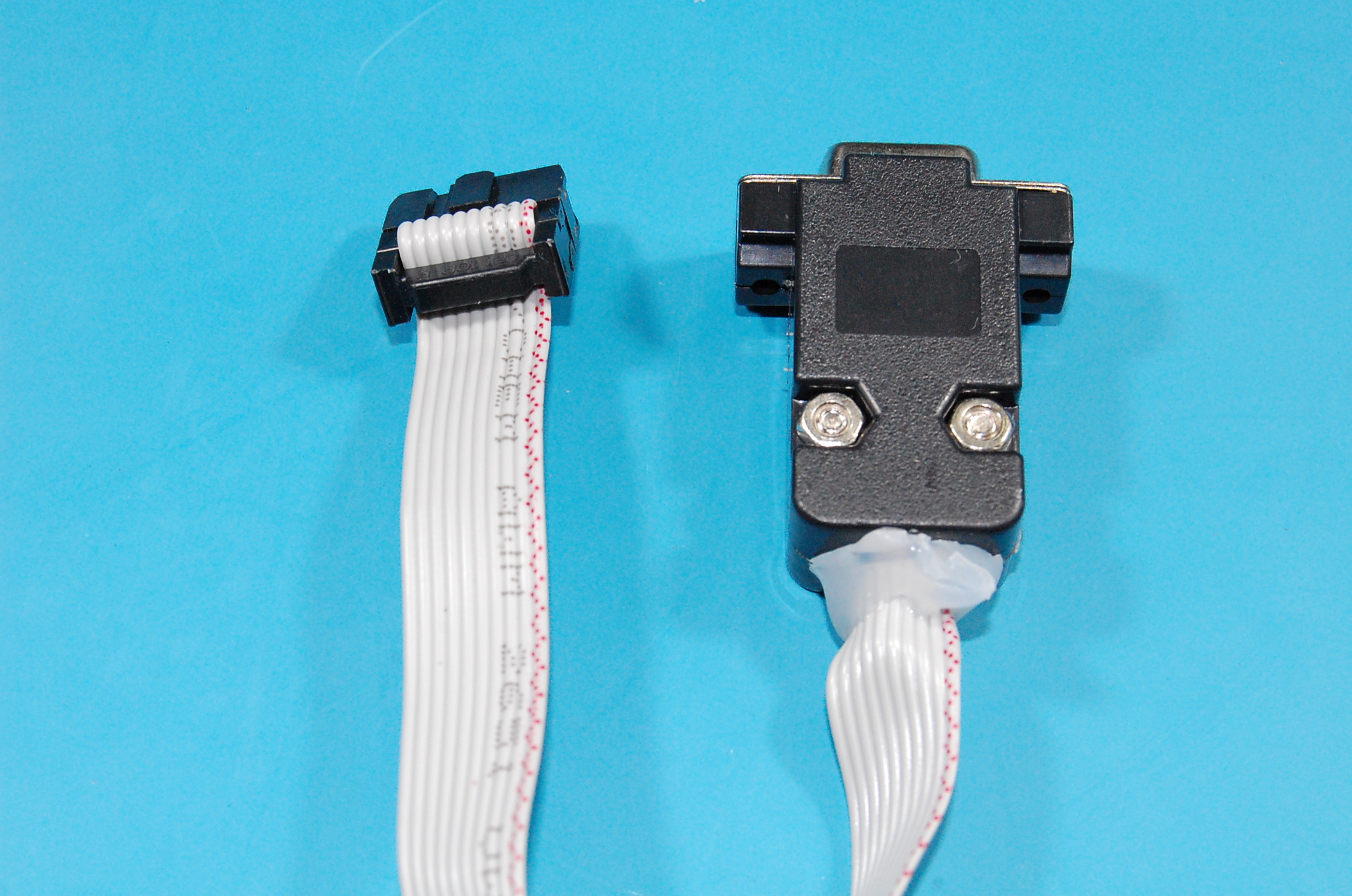
Assemble the shield
Assemble the shield. A simple way to protect the integrity of the cable (if you are using a ribbon cable) is to use hot glue.
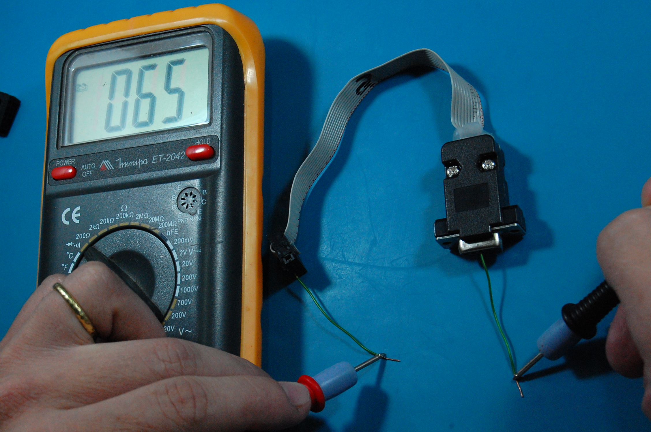
Verify the adapter integrity
Use a multimeter in the continuity tester mode to make sure that the cable is correctly assembled.