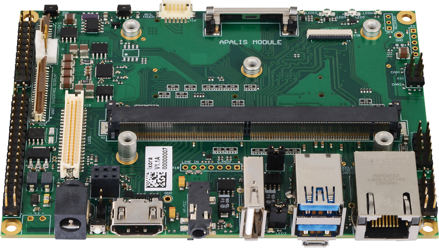
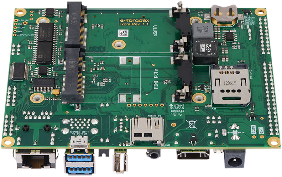
Ixora Carrier Board
Getting Started
This section contains initial information needed to set-up the Ixora Carrier Board for the first time.
Recommendation for a first-time order
Toradex recommends ordering the following additional products for your first-time order:
All the products can be ordered online at Toradex Webshop
Getting started for the first time?
For detailed step-by-step instructions about how to start with both, SoM and Carrier Board, please have a look at our step-by-step Getting-Started Guide:
Product-specific information for the Ixora Carrier Board:
Having trouble?
Please contact our technical support. Various option of technical support are mentioned in the article below.
Features
I/O Support
- USB 2.0 (1x Host, 1x OTG )
- USB 3.0 (2x Host)
- PCIe (1x Mini PCIe)
- I2C (2x)
- SPI (1x)
- UART (3x RS232)
- PWM (4x)
- GPIO (up to 40)
- Analog Input (4x)
- Ethernet (1x 10/100/1000 Mbit)
- SATA (1x mSATA)
- SDIO/SD/MMC (1x 4 Bit MicroSD)
- CAN (2x)
- LVDS (1x Dual Channel)
- S/PDIF In/Out (1x)
- HDMI (1x)
- RGB (1x 24 Bit)
- Resistive Touch (4/5-wire)
- Capacitive Touch connector
- Camera Parallel Interface (1x)
- Camera Serial Interface (1x)
- Analog Audio Line in (1x)
- Analog Audio Mic in (1x)
- Analog Audio Headphone out (1x)
- RTC on Board (1x)
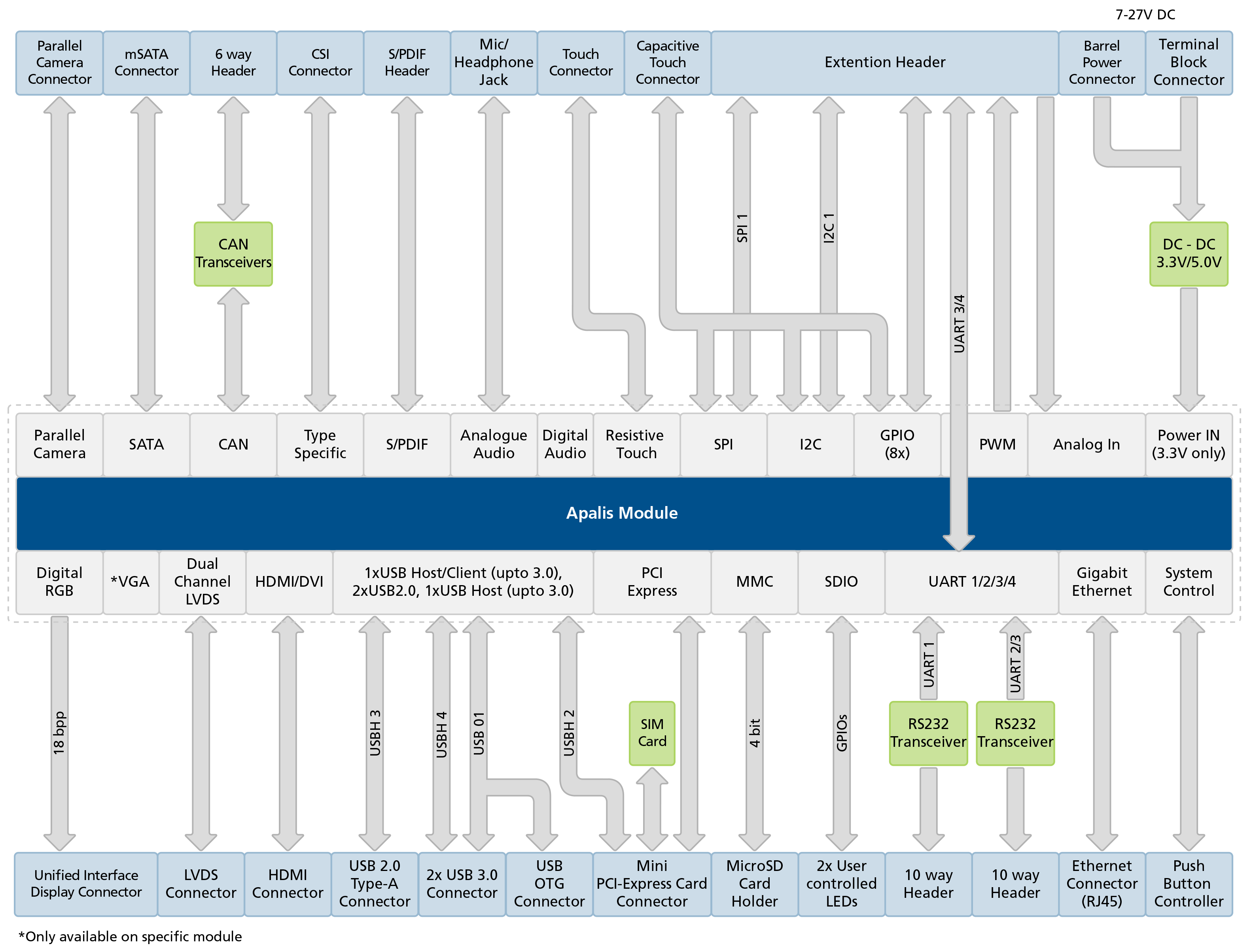
Block Diagram
Datasheets
Ixora V1.3 datasheet
Ixora V1.2 datasheet
Ixora V1.1 datasheet
Ixora V1.0 datasheet
Design Resources
Design data Ixora Carrier Board V1.3
Design data Ixora Carrier Board V1.2
Design data Ixora Carrier Board V1.1
Design data Ixora Carrier Board Archive
Ixora Carrier Board Mechanical Models
A basic 3D model for the Ixora Carrier Board V1.3 can be downloaded here:
- SolidWorks CAD model 3D EASM model
- You can download the free eDrawings model viewer from SolidWorks here
- 3D STEP model that can be opened and modified in any 3D CAD
- 3D PDF model that can be opened in Adobe Reader
Ixora Carrier Board V1.2 Models
- SolidWorks CAD model 3D EASM model
- You can download the free eDrawings model viewer from SolidWorks here
- 3D STEP model that can be opened and modified in any 3D CAD
- 3D PDF model that can be opened in Adobe Reader
Ixora Carrier Board V1.1 Models
- SolidWorks CAD model 3D EASM model
- You can download the free eDrawings model viewer from SolidWorks here
- 3D STEP model that can be opened and modified in any 3D CAD
- 3D PDF model that can be opened in Adobe Reader
Ixora Carrier Board V1.0 Models
- SolidWorks CAD model 3D EASM model
- You can download the free eDrawings model viewer from SolidWorks here
- 3D STEP model that can be opened and modified in any 3D CAD
- 3D PDF model that can be opened in Adobe Reader
Design and Layout Guide
Altium Designer
Compatible Products
- Apalis iMX8
- Apalis iMX8X
- Apalis T30
- Apalis TK1
- Apalis iMX6
- Apalis Heatsink
- Carrier Board Accessory Kit
- Apalis iMX6 Mezzanine
- Apalis T30 Mezzanine
- Analogue Camera Adapter
- Capacitive Touch Display 7" Parallel [1]
- Resistive Touch Display 7" Parallel
- Capacitive Touch Display 10.1" LVDS
- EDT Display
- LM816 USB WiFi
- CSI Camera Module 5MP OV5640 - for Ixora V1.1A and newer
[1] For Ixora V1.0A Capacitive Touch Adapter is required, V1.1A or above are directly compatible.
Revision History
Click to See the Product Numbering Scheme
Product Number (PID8) Format
The format of the 8-digits Product Number (PID8) is the following:
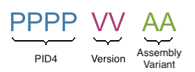
The below table describes the structure of the Product Number (PID8):
| Field | Description |
|---|---|
| PPPP | 4-digits number, indicating the Product Configuration (PID4) that describes the key properties of the product (e.g. Product Group, RAM capacity, etc.) |
| VV | 2-digits number, indicating the Major and Minor Version (in that order) |
| AA | 2-digits number, indicating the Assembly Variant |
See the complete list of available combinations on the Revision History table of the corresponding product page.
Example
Product number (PID8): 00291100:
0029: Apalis iMX6D 512MB
11: Major Version 1, Minor Version 1, Version V1.1 in short
00: Assembly Variant A
A specific product revision has a lifecycle defined by the product state. Learn more about it on the Product Change Notifications.
Ixora Carrier Board
PN: 0133
| Product # | Product Description | Changes from Previous Version | Release Date | PCN Document |
01331000 | Ixora V1.0A |
| 2013-09-26 | PCN Ixora Carrier Board V1.0A 2017-03-06 |
01331100 | Ixora V1.1A |
| 2017-03-24 | PCN Ixora Carrier Board V1.1A 2020-01-09 |
01331101 | Ixora V1.1B |
| 2019-05-07 | Interim version, no PCN. For details of changes in V1.2A, see PCN of V1.1A |
01331200 | Ixora V1.2A |
| 2020-01-09 | PCN Ixora Carrier Board V1.2A 2023-01-04 |
01331300 | Ixora V1.3A |
| Q2, 2023 |
Errata/Known issues
Errata Document
Issue trackers are not yet available in the new developer website. See it on the archived developer website.