Iris Carrier Board Peripherals
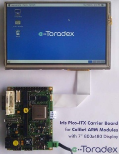
The Iris is a small form-factor(100mm x 72mm) off the shelf carrier board for the Colibri family.
Interfaces
Unified TFT interface
The Unified TFT interface is a standard from EDT[1]. It allows our customer to use a wide range of displays with our Iris board, without the need of an adapter print.

Example Setup
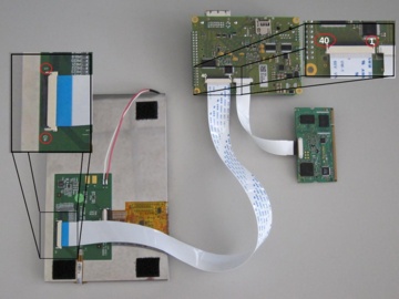
The following picture shows the setup of a Iris with a Colibri T20 and a Unified TFT interface display:

As shown in the picture, it is important to take in consideration the pin numbers indicated on the display and on the Iris carrier board in order to avoid damages on the devices.
Assembly Options
Since there are some small differences in the pin-out across the Unified TFT interface, some assembly options have been placed on the Iris board V1.1:
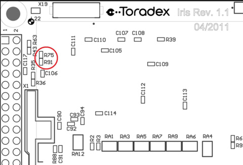
- For the models ET050080DH6 and ET050080DM6 the pin 34 is an active low Standby signal. Since on the Iris board this signal is set to GND by default, the resistor R91 needs to be disassemble and the resistor R75 needs to be assembled.
The following image shows the position of these resistors.

Make sure you also order an FFC 40 Pin 0.5mm cable for the display.
DVI-I display connector
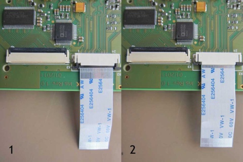
The connector X2 of Iris is the DVI-I display connector which can be used with the Colibri T20 and Colibri T30 modules. An FFC 24 Pin 0.5mm cable is included in the Iris package. The following image shows how to correctly connect this cable to the Iris board:

RS232 port on X13
X13 accepts a standard 10 pin IDC to 9 pin D-sub male connector. Unfortunately there are different standards. The standard we used is normally called DTK or Intel standard. Please check the pinout in the Iris Datasheet.
It is also very simple to build your own adapter using
- a regular 10 pin IDC female header
- some 10 way ribbon cable and
- a 10 pin IDC to 9 pin D-sub male connector.

You will further need a regular null modem aka cross-over cable to your PC's serial port or USB to serial adapter.
Signal Names to Colibri SODIMM Pins
| Signal Name | SODIMM Pin | Comment |
|---|---|---|
| PWM_A | 59 | Can be routed to X16 or X3 |
| PWM_B | 28 | |
| PWM_C | 30 | |
| PWM_D | 67 | |
| SSPFRM | 86 | |
| SSPSCKL | 88 | |
| SSPRXD | 90 | |
| SSPRXD | 92 | |
| BL_ON | 71 | Is on X7 and X3 |
Battery
The battery supplies the RTC with power while the system is off, so it does not lose track of the time.
You need a coin battery with with a voltage of min 2.3V and max 3.6V and 12mm diameter. (e.g BR1216, CR1216, BR1220, CL1220, CR1220, BR1225)