Toradex Camera Connector
The Toradex Camera Connector is a 24-pin, 0.5 mm-pitch Flexible Flat Cable (FFC) or Flexible Printed Circuit (FPC) interface used to connect MIPI CSI-2 cameras to Toradex carrier boards.
This article describes the connector pinout, electrical and mechanical specifications, and availability across Toradex carrier boards.
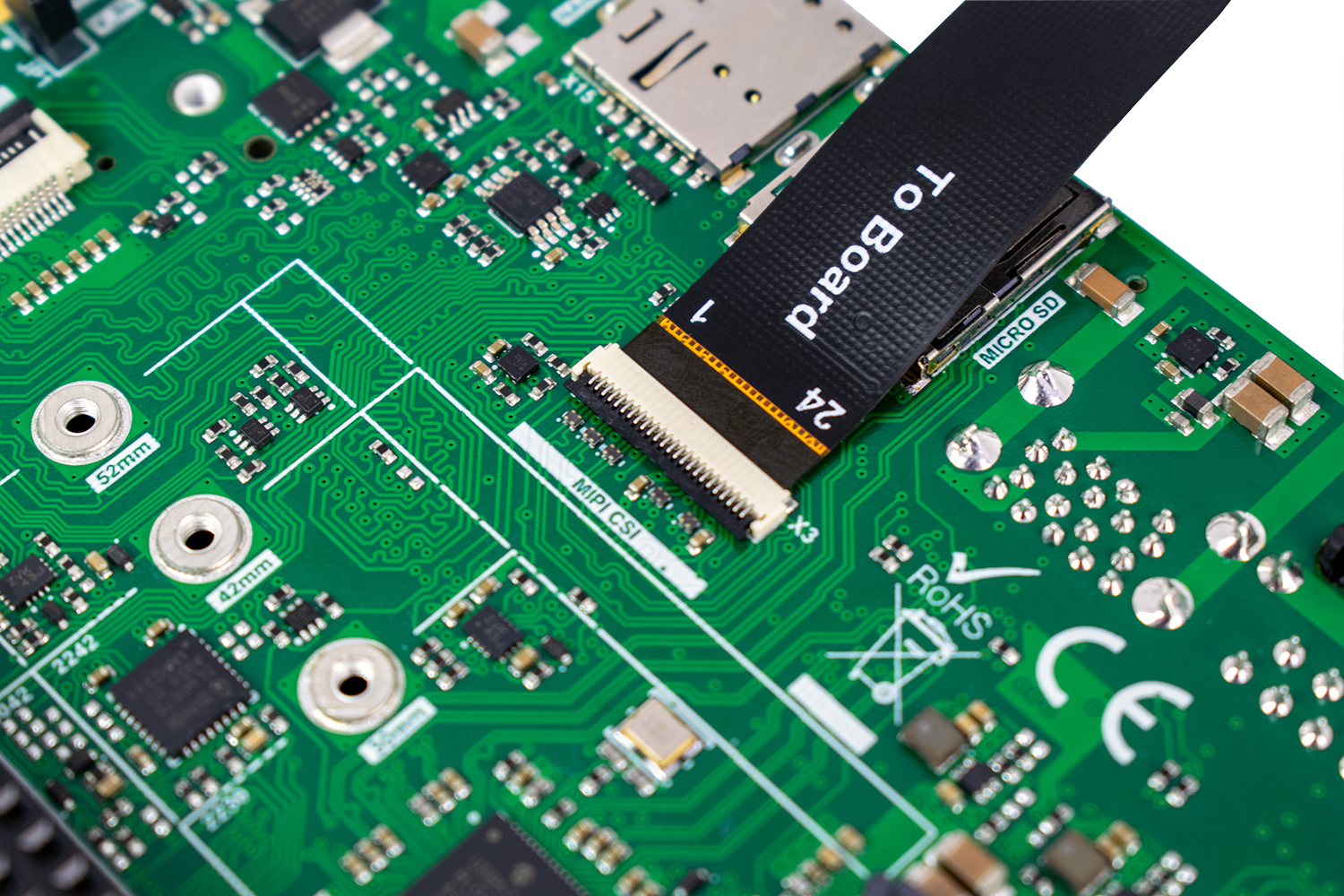
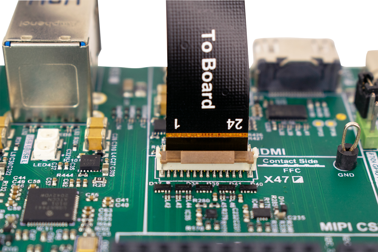
The connector provides a common pinout across several Toradex product families, with the following features:
- MIPI CSI-2 interface: Up to four D-PHY data lanes and one clock lane.
- Camera control: I2C communication, master clock (MCLK), reset, and power-control signals.
- Power supply: 3.3 V and 5 V rails for camera modules.
- Camera identification: An optional signal for identifying connected camera modules.
- Mechanical interface: A 24-position, 0.5 mm-pitch FFC/FPC connector.
For an overview of supported camera interfaces and recommended modules, see Cameras.
A matching 24-pin, 0.5 mm FFC/FPC connector does not guarantee compatibility. Verify the contact side, cable orientation, connector height, and insertion direction against the carrier board connector specifications and assembly drawing, and see the Board-Specific CSI-2 Connectors section before connecting a camera.
Power down the carrier board before connecting or disconnecting the camera, unless the hardware documentation explicitly states that the board supports hot-plugging.
Connector Pinout
The following table describes the common four-lane implementation. Signal names on individual carrier boards can differ slightly.
Directions are given from the carrier board and System on Module (SoM) perspective: In is an input, Out is an output, and N/A indicates that direction is not applicable.
| Pin | Generic Signal | Direction | Electrical Level | Description |
|---|---|---|---|---|
| 1 | GND | N/A | 0 V | Ground |
| 2 | CSI_D0_N | In | MIPI D-PHY | CSI-2 data lane 0, negative |
| 3 | CSI_D0_P | In | MIPI D-PHY | CSI-2 data lane 0, positive |
| 4 | GND | N/A | 0 V | Ground |
| 5 | CSI_D1_N | In | MIPI D-PHY | CSI-2 data lane 1, negative |
| 6 | CSI_D1_P | In | MIPI D-PHY | CSI-2 data lane 1, positive |
| 7 | GND | N/A | 0 V | Ground |
| 8 | CSI_CLK_N | In | MIPI D-PHY | CSI-2 clock lane, negative |
| 9 | CSI_CLK_P | In | MIPI D-PHY | CSI-2 clock lane, positive |
| 10 | GND | N/A | 0 V | Ground |
| 11 | CAM_RST | Out | 3.3 V logic | Camera reset |
| 12 | CAM_MCLK | Out | 3.3 V logic (*) | Camera master clock |
| 13 | CAM_I2C_SCL | In/Out | 3.3 V, open-drain | Camera control I2C clock, pulled up on the carrier board |
| 14 | CAM_I2C_SDA | In/Out | 3.3 V, open-drain | Camera control I2C data, pulled up on the carrier board |
| 15 | 3V3 | Power out | 3.3 V | Camera power supply |
| 16 | CSI_D2_N | In | MIPI D-PHY | CSI-2 data lane 2, negative |
| 17 | CSI_D2_P | In | MIPI D-PHY | CSI-2 data lane 2, positive |
| 18 | GND | N/A | 0 V | Ground |
| 19 | CSI_D3_N | In | MIPI D-PHY | CSI-2 data lane 3, negative |
| 20 | CSI_D3_P | In | MIPI D-PHY | CSI-2 data lane 3, positive |
| 21 | 5V | Power out | 5 V | Auxiliary camera power supply |
| 22 | CAM_PWRDWN | Out | 3.3 V logic | Camera power-down control |
| 23 | CAM_ID (optional) | In | 3.3 V logic | Optional camera identification input |
| 24 | CAM_PWRCTRL | Out | 3.3 V logic | Camera power-supply control |
(*) Verdin carrier boards are an exception and expose CAM_MCLK at 1.8 V. For details, see Single-Ended Camera Signals.
The original CSI Camera Module 5MP OV5640 uses only two CSI-2 data lanes, so pins 16, 17, 19, and 20 are not connected on that camera module. The connector itself still reserves these pins for a four-lane CSI-2 implementation.
Electrical Characteristics
MIPI CSI-2 Data and Clock
Pins 2/3, 5/6, 8/9, 16/17, and 19/20 carry the MIPI CSI-2 high-speed interface.
The interface uses MIPI D-PHY signaling. Carrier board routing must follow the applicable MIPI CSI-2 and Toradex carrier board layout requirements. Toradex reference designs route the differential pairs with 100 ohm differential impedance.
The number of usable data lanes depends on both the carrier board implementation and the installed SoM. A connector can physically provide four lane positions while a particular SoM or interface exposes fewer lanes.
Single-Ended Camera Signals
The following single-ended camera signals are defined at 3.3 V:
- Camera reset
- Camera master clock (MCLK)
- Camera control I2C
- Camera power-down
- Camera identification
- Camera power control
Carrier boards can use level translators between the SoM I/O voltage and the connector.
Verdin carrier boards are an exception where CAM_MCLK operates at 1.8 V instead of 3.3 V, as documented in the Errata HAR-8016 for the Verdin Development Board.
Always check the corresponding carrier board datasheet and schematics for the actual signal levels and implementation details before you design or connect a camera.
Camera I2C
Pins 13 and 14 provide the camera control I2C bus, which is defined to use 3.3 V pull-ups.
Do not assume a particular pull-up value when you design a camera module. Check the carrier board schematic and account for any additional pull-ups on the camera.
Power Supplies
The connector provides two supply rails:
| Pin | Supply | Purpose |
|---|---|---|
| 15 | 3.3 V | Main camera or module supply |
| 21 | 5 V | Auxiliary camera supply |
The available current depends on the carrier board. For the limits, see the carrier board datasheet.
A camera does not need to use both rails. For example, the CSI Camera Module 5MP OV5640 generates the sensor supply rails from the 3.3 V input and uses the 5 V input only for the flash LED.
Camera Control Signals
The control signals have generic functions, so different camera modules can use the same connector:
CAM_RST(pin 11) resets the image sensor or camera module.CAM_PWRDWN(pin 22) controls the camera power-down or standby function.CAM_ID(pin 23) is an optional camera identification input.CAM_PWRCTRL(pin 24) allows software-controlled camera power sequencing or power-supply control.
The active level and required sequencing of CAM_RST, CAM_PWRDWN, and CAM_PWRCTRL depend on the camera module. For details, see the camera hardware documentation and software integration instructions.
Connector Mechanics
The connector has the following mechanical characteristics:
| Parameter | Value |
|---|---|
| Positions | 24 |
| Pitch | 0.5 mm |
| Cable | FFC/FPC |
| CSI-2 lanes | Up to 4 data lanes and 1 clock lane |
Toradex has used multiple receptacle part numbers for this interface. Common examples include:
| Connector | Example Use |
|---|---|
Würth Elektronik 687124182122 | Ixora, Mallow, CSI Camera Module 5MP OV5640 |
Hirose FH12-24S-0.5SVA(54) | Verdin Development Board, Aquila Development Board, SMARC Development Board, Apalis Evaluation Board |
Hirose FH12-24S-0.5SVA(55) | Dahlia |
Hirose FH12-24S-0.5SH(55) | OSM Development Board |
Availability on Toradex Carrier Boards
Several product families use the Toradex Camera Connector. The table notes only deviations from the standard connector definition.
| Product Family | Carrier Board | Connector | Quantity | CAM_ID | Deviations and Notes |
|---|---|---|---|---|---|
| Apalis | Ixora V1.1A and newer | X28 | 1 | Yes | |
| Apalis | Apalis Evaluation Board V1.2 | X60 | 1 | Yes | |
| Apalis | Apalis iMX6 Mezzanine V2.0 | X4 | 1 | Yes | |
| Verdin | Verdin Development Board | X47 | 1 | Yes | MCLK 1.8 V |
| Verdin | Dahlia Carrier Board | X16 | 1 | Yes | MCLK 1.8 V |
| Verdin | Mallow Carrier Board | X3 | 1 | Yes | MCLK 1.8 V |
| Verdin | Yavia Carrier Board | J14 | 1 | Yes | MCLK 1.8 V |
| Aquila | Aquila Development Board | J70, J71 | 2 | Yes | |
| SMARC | SMARC Development Board | J45, J46 | 2 | No | J45 implements 2 CSI-2 data lanes. Pin 22 is not connected on either connector. |
| OSM | OSM Development Board | X27, X28 | 2 | No |
A carrier board that has the connector does not guarantee that every compatible Toradex SoM supports the same number of CSI-2 lanes, the same camera features, or the same software support. Always check the relevant SoM and carrier board datasheets and the carrier board schematics for the exact implementation and electrical characteristics.
Board-Specific CSI-2 Connectors
The connectors in this section expose MIPI CSI-2 but are not compatible with the Toradex Camera Connector, unless explicitly stated otherwise.
Apalis iMX6 Mezzanine V1.0A
The original Apalis iMX6 Mezzanine V1.0A, released in 2015, exposed its quad-lane CSI-2 interface through two 8-pin Molex 85508-5001 connectors:
- One connector carried the CSI clock, lane 0, camera I2C, 5 V, and ground.
- The second connector carried the remaining CSI data lanes.
This arrangement is not compatible with the Toradex Camera Connector.
Apalis iMX6 Mezzanine V2.0, released in 2018, was redesigned for compatibility with the CSI Camera Module 5MP OV5640.
Colibri iMX8X
The Colibri iMX8X, introduced in 2018, exposes a 24-pin, 0.5 mm MIPI CSI-2 FFC connector directly on the SoM as connector X3. Its pinout is largely compatible with the Toradex Camera Connector, with the following differences:
- Pin 21 is
GNDinstead of 5 V. - Pin 24 is not connected. On the Toradex Camera Connector, pin 24 is
CAM_PWRCTRL, the camera power-supply control signal.
History
The connector convention was introduced during the Apalis generation.
Ixora V1.1A, released on 2017-03-24, added the MIPI CSI connector X28. It is the earliest released Toradex carrier board implementation identified with the 24-pin, 0.5 mm camera connector pinout.
Verdin carrier boards and the Aquila, SMARC, and OSM development platforms later reused the pinout.