Thermal Management
Introduction
Thermal management ensures the system and its components operate within defined temperature ranges for reliable operation. It involves concepts such as power consumption, heat dissipation, and system temperature, which are related to the following topics:
- Hardware: the heat generation is directly proportional to the power consumption of the device. Also, each component has its specific operating temperature ranges and limits. Usually, you are concerned with System on Chip (SoC) heat dissipation and System on Module (SoM) operating temperature ranges. The optimal design of the carrier board may help reduce the power consumption of the system, which may result in a significant heat reduction.
- Software: the power consumption - and thus the heat generation - of the system and its components are affected by the software load put on the hardware components, such as CPU cores, GPU, and peripherals. This software load is directly related to the use-case application but also affected by the BSP version and its fine-tuning.
- Enclosing: the mechanical enclosing of the system - a box, for instance - must be taken into account when it comes to thermal management. A low-power SoM may fit a constrained enclosing, whereas a high-performance system may require a well-designed airflow or ventilation scheme for proper operation.
- Environment: heat flux intensity depends on a difference of temperature, which in our case is the difference between the hardware - usually the SoC in this case - and the environment. Knowing the environment temperature range where the system will operate is essential for designing a thermal management solution that both satisfies the system requirements and uses the least complex cooling mechanism possible.
This article provides an overview of thermal management solutions applied to the Toradex SoMs. It goes through the hardware and software BSP specifics as well as cooling solutions.
Hardware
This section goes through the hardware specifics related to thermal management.
Additional information can be found in the respective Toradex SoMs datasheets, under the Thermal Specification section. The datasheets are available in the corresponding product pages, under the Datasheets tab.
SoC (CPU) Limits
The following table provides the maximum junction temperature for a specific SoC. Notice that this is the maximum temperature at the semiconductor level, measured by a sensor internal to the SoC die. This temperature is higher than the die/case temperature and is monitored by the underlying operating system and/or additional hardware mechanisms. If temperature throttling mechanisms fail to keep the SoC from reaching the junction temperature, a forced system shutdown is issued to prevent permanent damage.
Browse the following dropdown table for information about maximum junction temperature sorted by SoC:
Maximum Junction Temperature by SoC
| Family | SoC | Max. Junction Operating Temperature (°C) | Thermal Resistance Junction-to-Ambient (°C/W) |
|---|---|---|---|
| Apalis | i.MX 8QuadMax | +125 | 11.7 |
| Apalis | i.MX 8QuadMax IT | +125 | 11.7 |
| Apalis | i.MX 8QuadPlus | +125 | 11.7 |
| Colibri | i.MX 8QuadXPlus IT | +125 | 15.2 |
| Colibri | i.MX 8DualX | +125 | 15.2 |
| Verdin | AM62 Quad IT | +105 | 22.3 |
| Verdin | AM62 Dual IT | +105 | 22.3 |
| Verdin | AM62 Solo IT | +105 | 22.3 |
| Verdin | i.MX 8M Mini DualLite | +95 | 22.9 |
| Verdin | i.MX 8M Mini DualLite IT | +105 | 22.9 |
| Verdin | i.MX 8M Mini Quad IT | +105 | 22.9 |
| Verdin | i.MX 8M Plus Quad | +95 | 20.44 |
| Verdin | i.MX 8M Plus Quad IT | +105 | 20.44 |
| Verdin | i.MX 8M Plus QuadLite IT | +105 | 20.44 |
| Colibri | i.MX7 Dual | +105 | 30.2 |
| Colibri | i.MX7 Solo | +105 | 30.2 |
| Apalis | i.MX6 Quad | +105 | 22.0 |
| Apalis | i.MX6 Quad IT | +105 | 15.0 |
| Apalis | i.MX6 Dual | +105 | 22.0 |
| Apalis | i.MX6 Dual IT | +105 | 15.0 |
| Colibri | i.MX6 DualLite | +95 | 23.0 |
| Colibri | i.MX6 DualLite IT | +105 | 23.0 |
| Colibri | i.MX6 Solo | +95 | 23.0 |
| Colibri | i.MX6 Solo IT | +105 | 23.0 |
| Colibri | i.MX 6ULL | +95 | 36.2 |
| Colibri | i.MX 6ULL IT | +105 | 36.2 |
| Apalis | Tegra K1 | +105 | 12.3 |
| Apalis / Colibri | Tegra 3 | +90 | 11.6 |
| Apalis / Colibri | Tegra 3 IT | +105 | 11.6 |
| Colibri | Tegra 2 | +90 | 18.7 |
| Colibri | Tegra 2 IT | +105 | 18.7 |
| Colibri | VF61 IT | +105 | 28.0 |
| Colibri | VF50 | +105 | 28.0 |
| Colibri | VF50 IT | +105 | 28.0 |
SoM Limits
The operating temperature of all the electrical components in an SoM defines the final module specification. As a consequence, the most critical element regarding temperature limits may not be the SoC, but instead another part. The following dropdown tables list the operating temperature range by Toradex SoM:
Apalis Family
Maximum Operating Temperature by Apalis SoM
| Module | Min. Operating Temperature (°C) | Max. Operating Temperature (°C) |
|---|---|---|
| Apalis iMX8 QuadMax 4GB Wi-Fi / Bluetooth IT | -40 | +85 |
| Apalis iMX8 QuadMax 4GB IT | -40 | +85 |
| Apalis iMX8 QuadPlus 2GB Wi-Fi / Bluetooth | -25 | +85 |
| Apalis iMX8 QuadPlus 2GB | -25 | +85 |
| Apalis iMX6 Quad 2GB IT | -40 | +85 |
| Apalis iMX6 Quad 1GB | 0 | +70 |
| Apalis iMX6 Dual 1GB IT | -40 | +85 |
| Apalis iMX6 Dual 512MB | 0 | +70 |
| Apalis TK1 2GB | -25 | +85 |
| Apalis T30 2GB | 0 | +70 |
| Apalis T30 1GB | 0 | +70 |
| Apalis T30 1GB IT | -40 | +85 |
Colibri Family
Maximum Operating Temperature by Colibri SoM
| Module | Min. Operating Temperature (°C) | Max. Operating Temperature (°C) |
|---|---|---|
| Colibri iMX8 QuadXPlus 2GB Wi-Fi / Bluetooth IT | -40 | +85 |
| Colibri iMX8 QuadXPlus 2GB IT | -40 | +85 |
| Colibri iMX8 DualX 1GB Wi-Fi / Bluetooth | -25 | +85 |
| Colibri iMX8 DualX 1GB | -25 | +85 |
| Colibri iMX7 Dual 1GB | -20 | +85 |
| Colibri iMX7 Dual 512MB | -20 | +85 |
| Colibri iMX7 Solo 256MB | -20 | +85 |
| Colibri iMX6 DualLite 512MB | 0 | +70 |
| Colibri iMX6 DualLite 512MB IT | -40 | +85 |
| Colibri iMX6 Solo 256MB | 0 | +70 |
| Colibri iMX6 Solo 256MB IT | -40 | +85 |
| Colibri iMX6ULL 512MB Wi-Fi / Bluetooth IT | -40 | +85 |
| Colibri iMX6ULL 512MB Wi-Fi / Bluetooth | 0 | +70 |
| Colibri iMX6ULL 512MB IT | -40 | +85 |
| Colibri iMX6ULL 256MB | 0 | +70 |
| Colibri T30 1GB | 0 | +70 |
| Colibri T30 1GB IT | -40 | +85 |
| Colibri T20 512MB | 0 | +70 |
| Colibri T20 512MB IT | -40 | +85 |
| Colibri T20 256MB | 0 | +70 |
| Colibri T20 256MB IT | -40 | +85 |
| Colibri VF61 256MB IT | -40 | +85 |
| Colibri VF50 128MB | 0 | +70 |
| Colibri VF50 128MB IT | -40 | +85 |
Verdin Family
Maximum Operating Temperature by Verdin SoM
| Module | Min. Operating Temperature (°C) | Max. Operating Temperature (°C) |
|---|---|---|
| Verdin iMX8M Mini Quad 2GB Wi-Fi / Bluetooth IT | -40 | +85 |
| Verdin iMX8M Mini Quad 2GB IT | -40 | +85 |
| Verdin iMX8M Mini DualLite 1GB Wi-Fi / Bluetooth IT | -40 | +85 |
| Verdin iMX8M Mini DualLite 1GB | 0 | +70 |
| Verdin iMX8M Plus Quad 4GB Wi-Fi / Bluetooth IT | -40 | +85 |
| Verdin iMX8M Plus Quad 4GB IT | -40 | +85 |
| Verdin iMX8M Plus Quad 2GB Wi-Fi / Bluetooth IT | -40 | +85 |
| Verdin iMX8M Plus Quad 2GB | 0 | +70 |
| Verdin iMX8M Plus QuadLite 1GB IT | -40 | +85 |
Software and BSP
This section goes through the software and BSP specifics related to thermal management.
Dynamic Voltage and Frequency Scaling (DVFS) and Thermal Throttling
Dynamic Voltage and Frequency Scaling (DVFS) is a mechanism in which the operating system optimizes power consumption by adjusting the CPU clocks and voltage based on demand. A side-effect of power consumption optimization is that the system generates less heat in workloads that don't make full use of the CPU.
Thermal Throttling is a mechanism implemented in the operating system to preserve the integrity of the processor. It forces reduction of the system clock when the processor reaches certain temperatures, independent of DVFS.
DVFS is disabled by default on WinCE. See DVFS on Windows Embedded Compact for further information.
CPU Hotplug
See the following articles for detailed information on supported modules:
OS Specific Guidelines
Choose your OS from the following tabs:
- Linux
- WinCE
Using Linux, DVFS can be disabled, and the CPU frequency manually set. See the CPU Frequency (Linux) article.
An application in the userspace can monitor the temperature. How to read it and which sensors are available is module-dependent. See the Temperature Sensor (Linux) article and Apalis/Colibri T30 Temperature Monitoring for additional information.
The Linux kernel executes the Thermal Throttling, and the generic Thermal Sysfs API provides access to its settings. The following section includes information about how to set temperature trip points in Linux:
How to Set Temperature Trip Points
There are two temperature trip points used on iMX SoCs.
- passive: This is the point where Linux starts to throttle the CPU.
- critical: This is the point where Linux shuts itself down to protect the CPU.
Toradex decided to use the T_junction_max stated in the datasheet for the critical temperature and 10°C less for the passive trip point.
The following patch should be a guideline how to change these trip-points for iMX related SoCs:
i.MX 6(ULL) / i.MX 7
diff --git a/drivers/thermal/imx_thermal.c b/drivers/thermal/imx_thermal.c
index 28072a7..591d6be 100644
--- a/drivers/thermal/imx_thermal.c
+++ b/drivers/thermal/imx_thermal.c
@@ -656,10 +656,10 @@ static int imx_get_sensor_data(struct platform_device *pdev)
     }

     /*
-     * Set the critical trip point at 5C under max
+     * Set the critical trip point at max
      * Set the passive trip point at 10C under max (can change via Sysfs)
      */
-    data->temp_critical = data->temp_max + (1000 * 10);
+    data->temp_critical = data->temp_max;
     data->temp_passive = data->temp_max - (1000 * 10);

     return 0;
data->temp_max in this driver is used for the T_junction_max that is read out from the fuses.
data->temp_passive and data->temp_critical are the temperatures described above that a developer should set with the desired temperature in milli-degree Celsius.
i.MX 8/8X/8M Mini/8M Plus
The i.MX 8/8X power management and temperature monitoring are entirely handled by the System Controller Firmware (SCFW).
The critical and passive points threshold set in their dtsi file and specify CONFIG_IMX8M_THERMAL in defconfig.
The thermal driver can be accessed through the following interface:
/sys/class/thermal/thermal_zoneXfor i.MX 8 and i.MX 8X./sys/class/thermal/thermal_zone0for i.MX 8M Mini./sys/class/thermal/thermal_zoneXfor i.MX 8M Plus.
Inside the preceding directory, there are files named trip_point*. There you can read the type, current temperature, and hysteresis used by those trip points.
If you want to change the trip points, and you are using an i.MX 8M Mini/8M Plus, it will require a deeper understanding of how they are configured by the system. There are two cases:
- The temperature trip points for the thermal zones are edited by U-Boot considering the SoC that was detected at runtime.
- The trip points that are set on the kernel device tree are used by the NXP “wait for cooling” feature in U-Boot. Whenever U-Boot detects that the SoC is too hot, it stops the boot process and waits until the temperature is lower than the thresholds that are defined in the device tree.
Editing the trip points directly on the device tree only affects the cooling feature in U-Boot (2nd case), but in this case, they are not persistent between boots. If you need the configuration to be persistent, it is possible to edit the trip points using sysfs, in which a systemd service can be created to perform the edit on boot.
How to Set Temperature Trip Points
DVFS and temperature throttling settings can be customized. See the Resource Manager Registry Settings and Apalis/Colibri iMX6 DVFS on Windows Embedded Compact articles. As an alternative to tweaking resources, as well as a means to monitor system frequency and temperature, Toradex provides a software tool named Toradex Task Manager. Notice that DVFS is available from WinCE Image 1.3b4 onwards.
For additional temperature monitoring information, see Apalis/Colibri T30 Temperature Monitoring and SoC Temperature Readout (WinCE).
Tips and Recommendations
This section has some tips on how to save power, which may help reduce heat generation and other aspects of the software that may affect thermal management.
Disable Unused Display Interfaces
Disabling display interfaces your application doesn't use reduces the power draw associated with driving them, which helps reduce heat generation.
- Linux: Display Output, Resolution, and Timings (Linux)
- WinCE: Tegra display driver registry settings
Use a Lower Frequency
Lowering the CPU frequency reduces power consumption and heat generation, at the cost of processing performance. Test the effect on your use case before applying it permanently.
- Linux: CPU Frequency (Linux)
- WinCE: Toradex Task Manager
Avoid Toggling Pins
Make sure none of the pins are unnecessarily toggling, and that all input pins are in a defined state. Unnecessary pin activity increases power consumption and heat generation.
- Linux: GPIO command-line tools and Device Tree Customization
- WinCE: GPIO Config
Use Low Power Modes
Enter Suspend mode during idle time, or switch off the module completely, to reduce power consumption and heat generation when the system is not in active use.
- Linux: Suspend/Resume (Linux)
- WinCE: Toradex WinCE images offer fast boot, in some cases with a boot time of less than 0.5 seconds.
Check CPU Load
Monitor the CPU load to identify unexpectedly high usage. Some easy modifications may help lower the CPU load, for example, using interrupts instead of polling or sleep instead of busy waits.
- Linux: Use tools such as
topandhtopto monitor CPU load. - WinCE: Use Toradex Task Manager to check the CPU load.
Disable Unused Drivers
Disabling drivers you don't use can help reduce power consumption. Measure the effect first, since disabling some drivers may negatively affect power consumption in certain cases.
We recommend measuring the system's power consumption before and after making the changes. It helps in getting a better understanding of the power management of the system.
Mechanical Considerations - Cooling Solutions
Cooling solutions usually target the SoC and can be either passive or active. Passive means that the natural convection transports the heat from the surface to the air. Passive cooling includes exposing the SoC to the environment with or without a heatsink. The efficiency of natural convection is dependent on the housings and the environment. This solution has no moving parts and does not produce noise. If the passive cooling is not sufficient, the most common active cooling solution for embedded systems is the use of a DC fan on top of the heat sink, which increases efficiency dramatically.
If a box encloses the hardware, there are two recommended approaches:
- The design of the enclosure should optimize the airflow.
- The enclosure should thermally couple to the SoC.
The temperature inside the enclosing has to respect the SoM operating temperature range.
Apalis
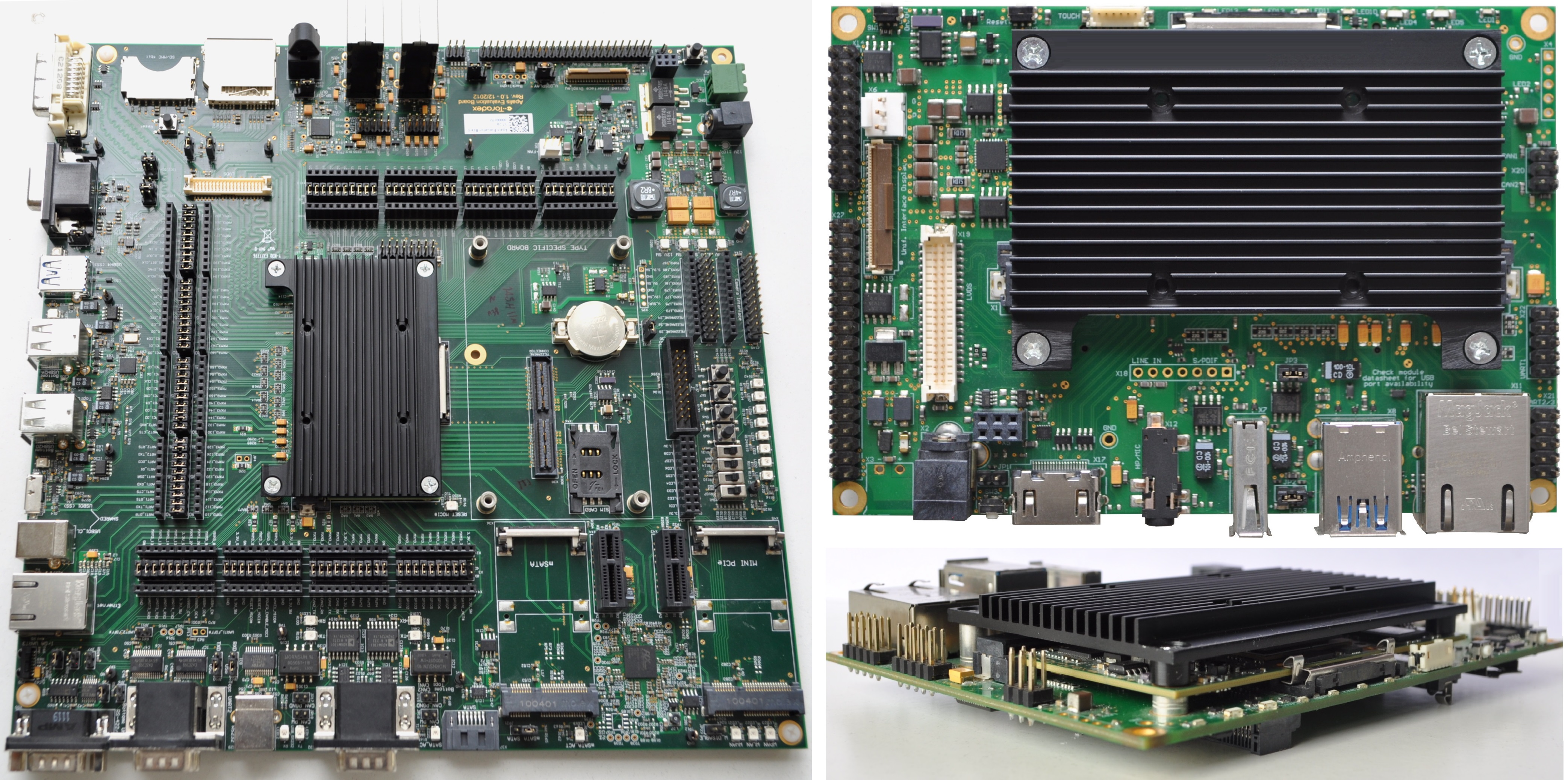
The Apalis family has a robust, rigid mounting mechanism to support thermal solutions. It is ready-to-use on Toradex carrier boards and, if you plan to design your carrier board, the thermal solution implementation guidelines are available in the Apalis Carrier Board Design Guide.
The optimized Apalis Heatsink is available for each version of the Toradex Apalis module. The following table shows the compatibility of the available Apalis heatsinks:
| Apalis Heatsink Type | Compatible Module |
|---|---|
| Type 1 | Apalis iMX6Q IT Apalis iMX6D IT |
| Type 2 | Apalis T30 |
| Type 3 | Apalis iMX6Q Apalis iMX6D Apalis TK1 |
| Type 4 | Apalis iMX8QM |
The Apalis heatsink has four holes intended for mounting a fan on top of it. Specifics are available in the Apalis Heatsink Fan article. Also, a 3D CAD model of the heatsink is available in the 3D CAD models page.
Colibri
The Colibri family of SoMs does not have a cooling solution officially provided by Toradex. Nevertheless, we have tested a few off-the-shelf heatsink solutions available in the market with Colibri T20 and T30 modules. For more details, see the following test reports:
Verdin
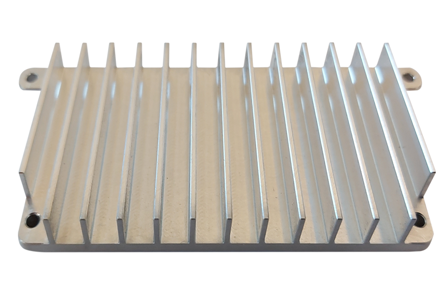
The Verdin family has a robust, rigid mounting mechanism to support thermal solutions. It is ready-to-use on Toradex carrier boards and, if you plan to design your carrier board, the thermal solution implementation guidelines are available in the Verdin Carrier Board Design Guide.
The optimized Verdin Industrial Heatsink is available for each version of the Toradex Verdin module. The following table shows the compatibility of the available Verdin Industrial Heatsink:
| Verdin Heatsink Type | Compatible Module |
|---|---|
| Type 1 | Verdin iMX8M Mini Verdin iMX8M Plus |
Legacy Information
Colibri PXAxxx
Colibri PXAxx modules run at a fixed frequency. Toradex provides ways to manually change the system frequency to tweak or optimize the system performance using software configurations. In most of the use cases, a cooling solution is not necessary. The maximum temperature is the case temperature of the PXA processor, which must not exceed 85°C. For more details, see the respective Colibri module datasheet and Marvell's EMTS.