Installing EDT Display
This article links to a Product which is going towards EOL (End of Life). Depending on your local Toradex entity, there are very few to none of this product left for sales.
Please also have a look at the main page about EDT Displays.
Cable Connection
When connecting the EDT displays to a Colibri Evaluation Board or an Iris carrier board, make sure that pin 1 of the display is connected to pin 1 of the board. Due to the nature of the FFC connectors, it is possible to invert the pinout and possibly damage the display and/or carrier board.
- The EDT 7" and EDT 5.7" display connectors do have contacts on top and bottom side.
- The Iris Carrier Board also has contacts on top and bottom side of the FFC connector.
- The FFC connector on the Colibri Evaluation Board has only contacts on the side towards the board edge.
Be also careful with the brown levers on the connectors. They are very delicate and can easily break.
Connection to the Colibri Evaluation Board V3.1
Please have a look at the pictures below which show how to connect the cables:
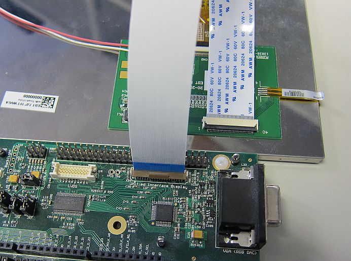
Connecting the EDT 7" display to the Colibri Evaluation Board V3.1
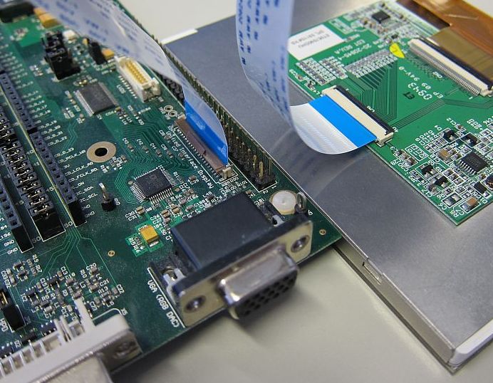
Connecting the EDT 5.7" display to the Colibri Evaluation Board V3.1
Installation on Win CE
Resolution
- Download the ColibriTweak zip file from the Toradex download section:
https://files.toradex.com/Colibri/WinCE/Colibri_Software/ColibriTweak/. It contains:
- The latest ColibriTweak Tool
- The display presets folder
- Connect the display with the provided FFC to the Iris Carrier Board or Evaluation Board paying attention to the pin numbering which is on the display and on the carrier board.
- Copy Colibri Tweak including the Display Preset folder to the Colibri (AciveSync, SD Card, USB Memory Stick, CF Card,..).
- Start Colibri Tweak. If you do not have a working display, use the Remote Display tool.
- In Colibri Tweak select the display preset "EDT_ET05709_640x480" if you are using the VGA or "EDT_ET070080_800x480" if you are using the WVGA display.
- For display specific settings see: EDT 7" WVGA Display or EDT 5" VGA Display
- Adjust the splash screen settings. This is particularly important for newer displays because they need proper resolution and timings at boot. You find more information about this here.
Brightness
For Colibri modules, if you connect it with a standard Colibri Carrier board you may experience that the display does not show to maximum brightness. To get the maximum brightness you need to set the back-light PWM_A signal to output 0.
| Module | Signal Name | SODIMM Pin/MXM pin | GPIO Pin | Display Pin |
|---|---|---|---|---|
| Colibri PXA270 | PWM_A | 59 | 12 | 6(LEDCTRL) |
| Colibri PXA300 | PWM_A | 59 | 20 | 6(LEDCTRL) |
| Colibri PXA310 | PWM_A | 59 | 20 | 6(LEDCTRL) |
| Colibri PXA320 | PWM_A | 59 | 14 | 6(LEDCTRL) |
| Colibri T20 | PWM_A | 59 | B4 Note1 | 6 (LEDCTRL) |
| Colibri T30 | PWM_A | 59 | B4 Note1 | 6 (LEDCTRL) |
| Colibri VF50 | PWM_A | 59 | PTC7 | 6 (LEDCTRL) |
| Colibri VF61 | PWM_A | 59 | PTC7 | 6 (LEDCTRL) |
Note1: SODIMM pin 59 on Colibri T20 and T30 has two CPU signals assigned (multiplexed) L5 and B4. Make sure you set B4 to output 0 and L5 to input.
Whereas, for Apalis T30 on a standard Apalis carrier board use GPIO C.00.
| Module | Signal Name | MXM Pin | GPIO Pin | Display Pin |
|---|---|---|---|---|
| Apalis T30 | BKL1_PWM | 239 | C.00 | 6 (LEDCTRL) |
For a test you can use the GPIOConfig Tool.
To make it permanent you need to set/create the following registry keys for the following modules:
| Module | Registry Location | BL_GPIO | BL_POL | DISP_GPIO | DISP_POL |
|---|---|---|---|---|---|
| Colibri PXA270 | [HKLM\Drivers\Display\Colibri] | 12 | 0 | 81 | 1 |
| Colibri PXA300 | [HKLM\Drivers\Display\Colibri] | 20 | 0 | 39 | 1 |
| Colibri PXA310 | [HKLM\Drivers\Display\Colibri] | 20 | 0 | 39 | 1 |
| Colibri PXA320 | [HKLM\Drivers\Display\Colibri] | 14 | 0 | 49 | 1 |
| Colibri T20 | [HKLM\Software\NVIDIA Corporation\NVDDI\LCD] | 12 | 0 | 156 | 1 |
| Colibri T30 | [HKLM\Software\NVIDIA Corporation\NVDDI\LCD] | 12 | 0 | 170 | 1 |
| Colibri VF50 | [HKLM\Drivers\Display\Colibri] (Image already has in built registry keys.) | 71 | 1 | N/A | N/A |
| Colibri VF61 | [HKLM\Drivers\Display\Colibri] (Image already has in built registry keys.) | 71 | 1 | N/A | N/A |
| Apalis T30 | [HKLM\Software\NVIDIA Corporation\NVDDI\LCD] | 16 | 0 | 170 | 1 |
For example, if you want to set values for Colibri T20 then set/create the registry keys as:
[HKLM\Software\NVIDIA Corporation\NVDDI\LCD]
BL_GPIO  = dword:0x0000000c    ; Backlight GPIO (GPIO B4 on T20/T30)
BL_POL   = dword:0             ; Backlight Polarity
DISP_GPIO= dword:0x0000009c    ; Display Enable GPIO (GPIO T4)
DISP_POL = dword:1             ; Display Enable Polarity
- Please note: due to a limitation of the Registry Editor in interactive mode, first create only the key [HKLM\Software\NVIDIA Corporation\NVDDI\LCD]. Then exit and restart the registry editor, before adding the values (BL_GPIO ...).
- Don't forget to save the registry.
- For more information about this registry keys see: Display Driver Registry Settings
- For the translation of alphanumeric GPIO identifiers to numeric ones see: GPIO Alphanumeric to GPIO Numeric Assignment
Touch Screen Calibration on Win CE
The EDT display are also featuring the touch screen interface on the same FFC.
To calibrate the touchscreen see: Touch Screen => Calibration
To make the calibration permanent, you need to save the registry.
Installation on Embedded Linux
Please find the instructions in the Display Output, Resolution and Timings and Resistive Touch Screen articles.