Display drive strength configuration
Display signals are big contributors to EMC emissions, especially in devices featuring large displays.
In order to minimize such emissions, it is often a good practice to increase the impedance (reduce the drive strength) of the signal drivers. On the other side, the impedance must not be too high, otherwise the digital signals cannot switch fast enough to drive the display properly. Some modules also allow to configure additional parameters such as slew rate and pad speed.
Example
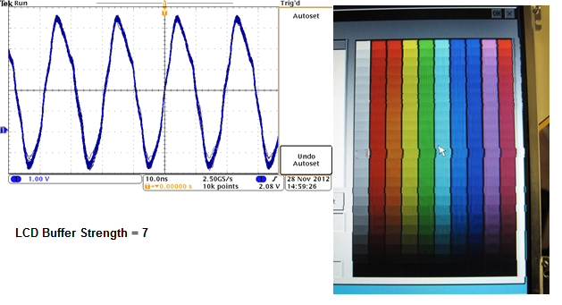
The image below shows one example of a system, where the drive strength was configured too high, and signal reflections caused a wrong picture. In this case the solution was to decrease the drive strength in order to minimize reflections.
Configure Signal Drivers
The available signal driver configuration options are SoC (and therefor Module) specific.
The Tegra 2/3 based modules allow to configure drive strength and slew rate for the falling and rising edge.
The NXP/Freescale based products typically allow to configure drive strength (output impedance), slew rate (how fast the pin toggles between two logic states) and speed (electrical characteristics of a pin in a frequency range). The NXP/Freescale application note AN5078 explains the effect of those configuration options in detail.
WinCE
In WinCE, the configuration options for the drive strength can be adjusted in the registry.
Details are described in the article display driver registry settings, look for the lcdbs registry key.
Linux
NXP/Freescale based modules allow to configure the signal driver settings as part of the pad settings in the device tree. Refer to the Device Tree Customization article for detail. The settings of SPEED, SRE (slew rate) and DSE (drive strength) can affect EMC emissions.