First Steps with Vision Components MIPI Camera Modules (Linux)
Introduction
This article describes how to start working with Vision Components VC MIPI CSI-2 camera modules.
The VC MIPI modules supported in this article share common software components, such as the camera driver and device tree overlay. Therefore, you can use Vision Components Yocto Project layers to build images for all supported camera modules.
Main Features
This article covers the following Vision Components MIPI modules:
IMX327C
Camera Module Features:
- Sensor: IMX327 from Sony® (improved version of the IMX290)
- Variant: Color (C)
- Sensor Resolution and Optical Format: 2MP CMOS Image Sensor, 1/2.8" optical format
- Native Resolution: 1920×1080 (Full HD)
- Sensor Type: CMOS Electronic Rolling Shutter Sensor
- Interface: MIPI CSI-2
Sensor Features:
- Pixel size: 2.9μm × 2.9μm
- Shutter type: Rolling Shutter
- Max frame rate: 60 fps at 10-bit (full resolution)
The IMX327 is a low-light optimized sensor, which makes it a common choice for surveillance, automotive, and machine-vision applications operating in poor lighting conditions.
Hardware Documentation
VC MIPI IMX327C Hardware Operating Manual
Compatible Products
Hardware
The following Toradex carrier boards that support the MIPI CSI-2 interface connect to the camera kits out-of-the-box, hardware-wise:
This camera module is supported for the following SoMs:
Software
To integrate the camera on the software side, you need to add Vision Components Yocto Project layers to an image built on top of the Toradex Linux BSP. This guide targets the Scarthgap (BSP 7) release.
Hardware Setup
What I Need to Order
The VC MIPI modules are part of a modular system. Hence, you can order each part (camera module, connector cable and lens) separately.
See the compatible products.

The following list describes all components that you should order:
-
Camera Module — Currently this guide documents the following VC MIPI camera module:
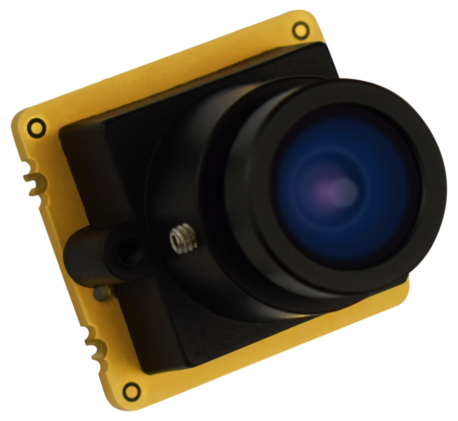
- VC MIPI IMX327C (2MP/1080p color optical sensor module, Sony® STARVIS™).
-
FPC Cable — The FPC cable connects the camera module to the carrier board and must match your processor board.
- 22-pin FPC cable (module side), in the length and board variant suitable for your carrier board.
-
Lens and Lens Holder — The module is shipped without optics. A lens and a matching lens holder are ordered separately.
- Lens holder for S-mount, C-mount, or CS-mount lenses.
- Lens matching the chosen holder and your application.
Where Do I Order
You can order the Toradex computer-on-modules and carrier boards online in the Toradex Webshop.
You can order the Vision Components camera module and accessories by directly contacting Vision Components.
Cable Connection
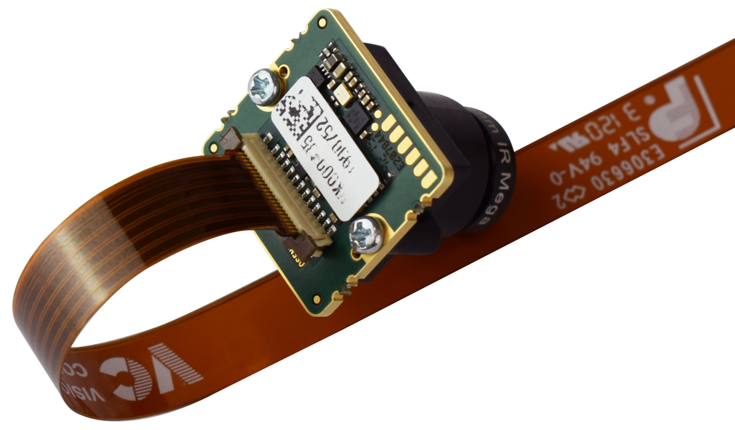
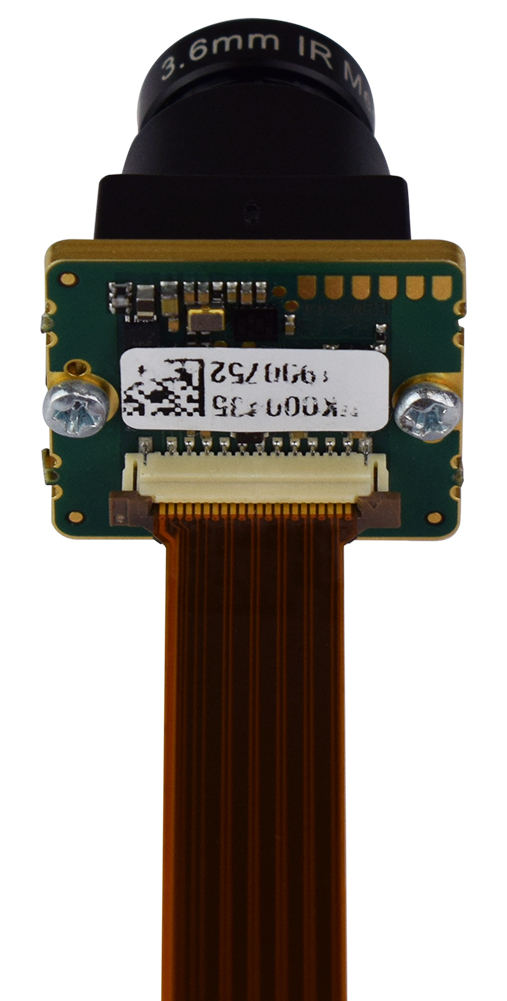
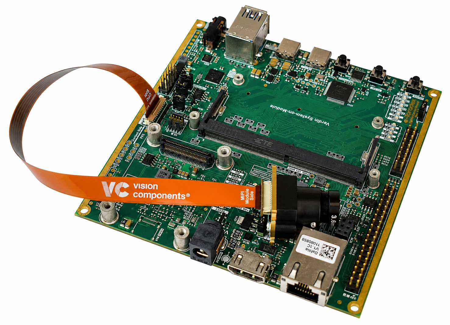
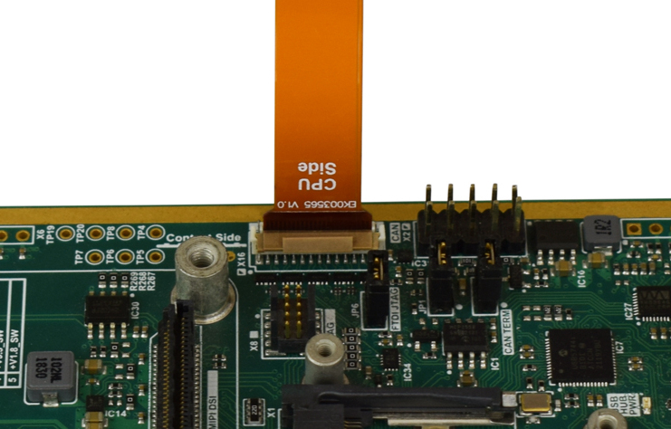
Connect the flat cable to the camera module, making sure the correct side of the cable faces the module and the board, as shown in the following pictures:
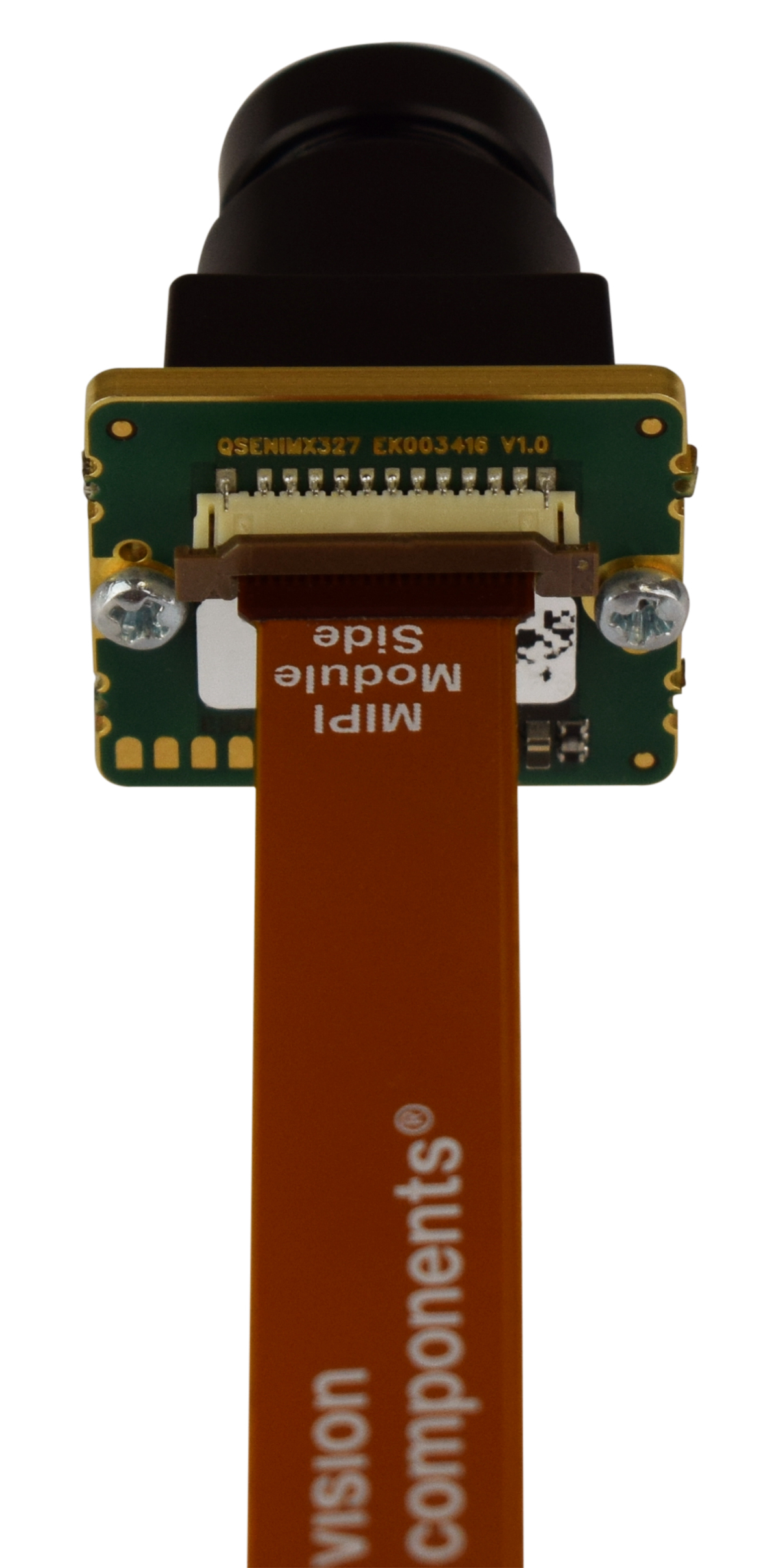
Please disconnect any power and USB cables from the board before connecting the flat cable to the MIPI CSI-2 bus to avoid any damage to the camera!
Connection to Dahlia Carrier Board
- For the Dahlia Carrier Board, the MIPI-CSI camera interface is on connector X16.
Connection to Mallow Carrier Board
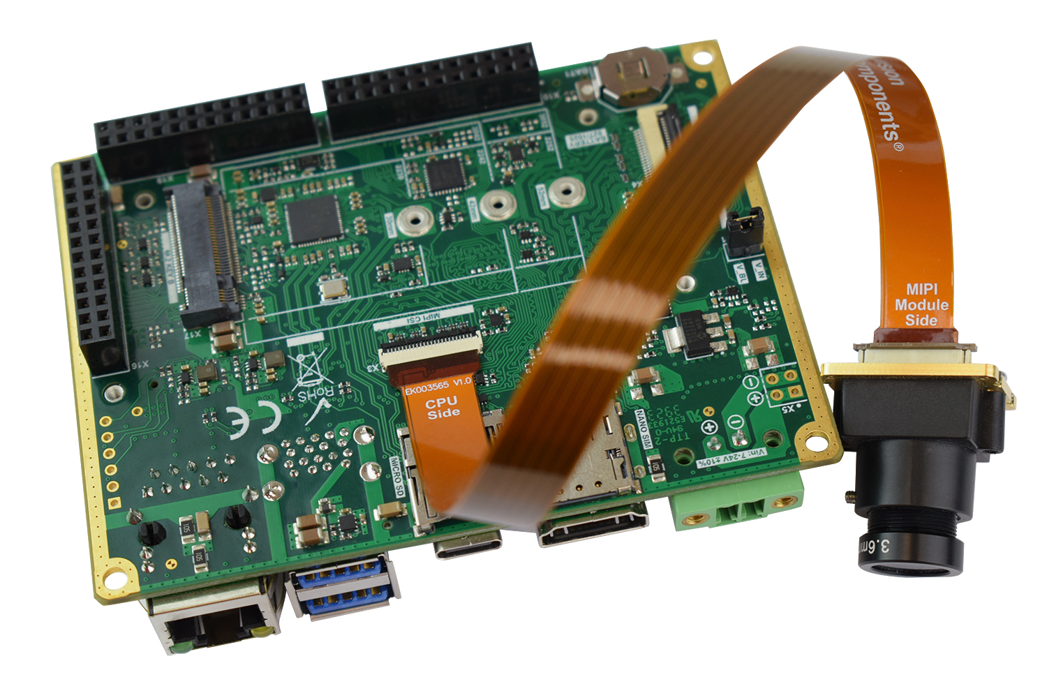
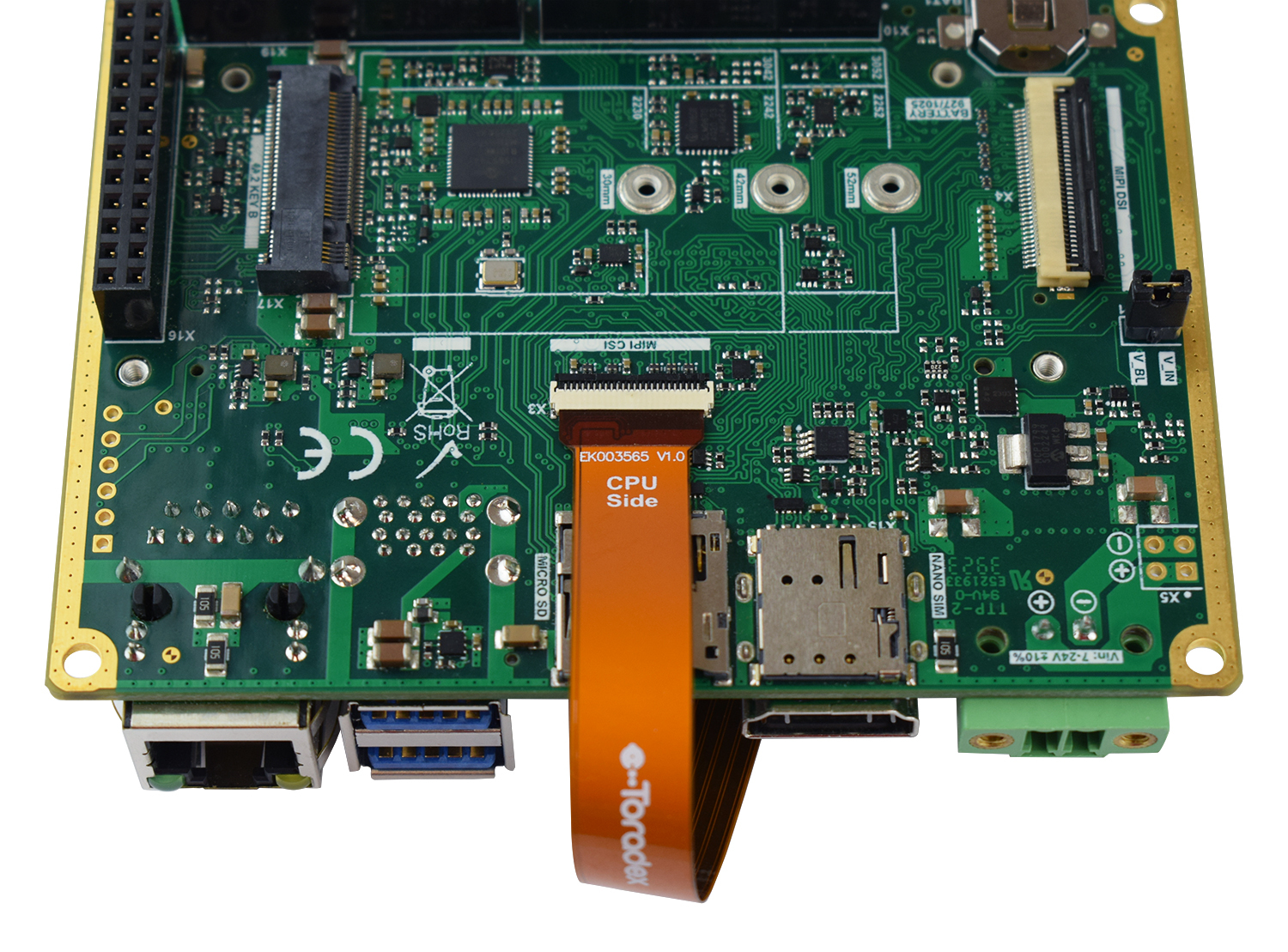
- For the Mallow Carrier Board, the MIPI-CSI camera interface is on connector X3.
Connection to Verdin Development Board
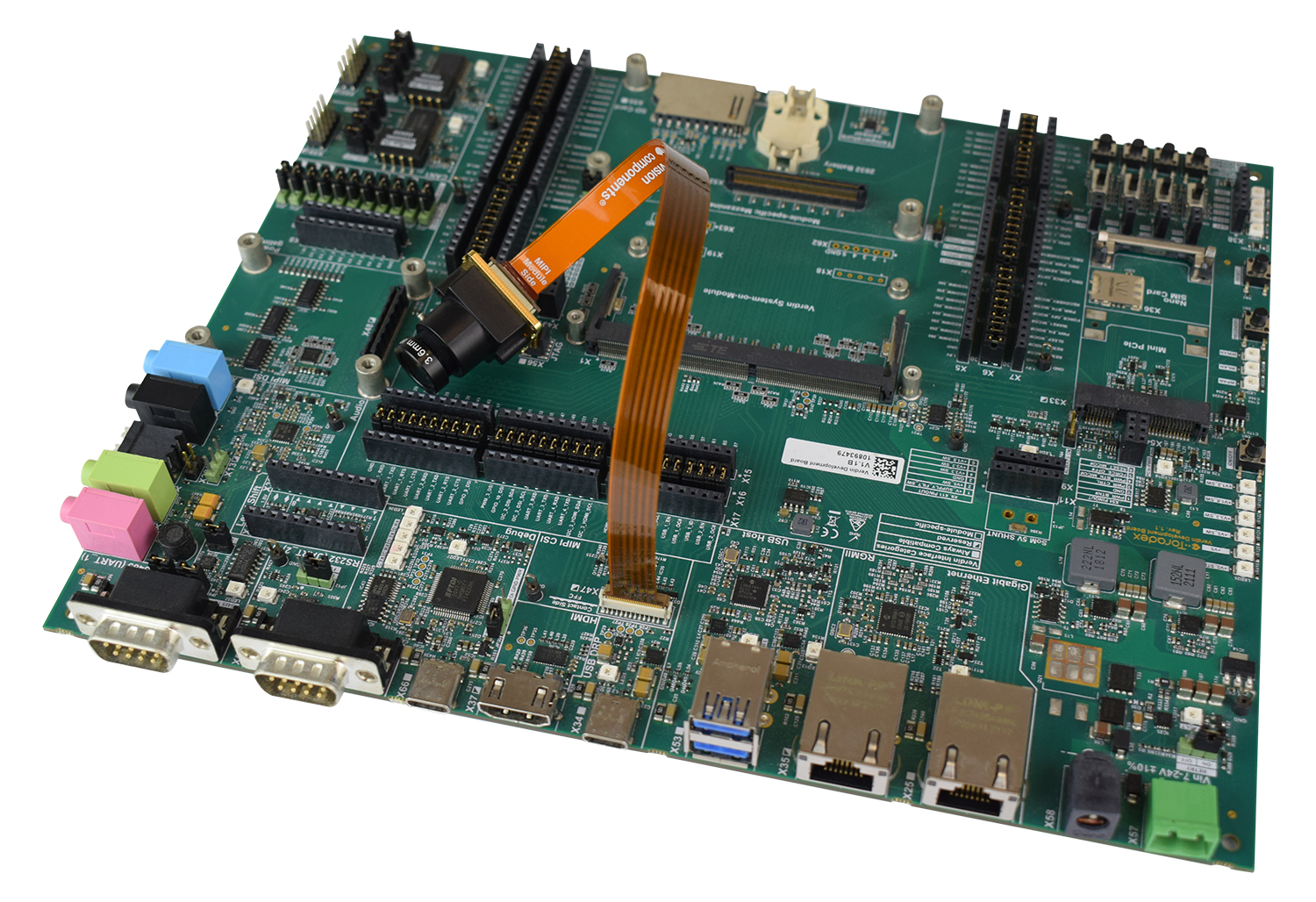
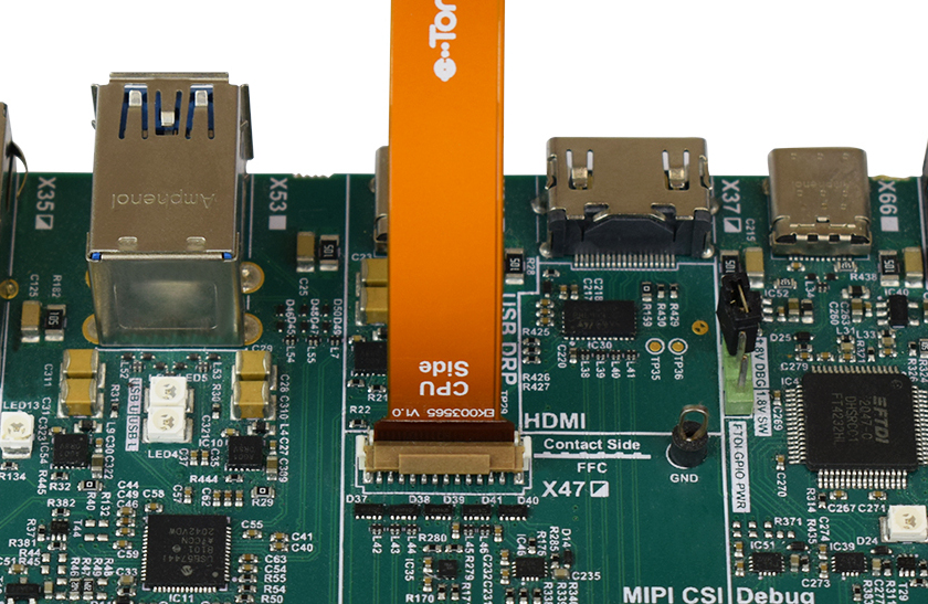
- For the Verdin Development Board, the MIPI-CSI camera interface is on connector X47.
The flat ribbon cable used to connect the carrier board and the camera adapter is fragile. If your camera does not work, make sure to test the cable connections.
Building the Image
The Toradex BSP integrates with the Vision Components Yocto layers through a repo manifest.
This section covers the Vision Components integration workflow. For the underlying Toradex build environment, refer to Build a Reference Image with Yocto Project/OpenEmbedded.
1. Set Up the Environment
Make sure your host meets the prerequisites for building a reference image, including the repo tool.
2. Initialize and Sync the Manifest
Initialize the Vision Components manifest for the toradex-scarthgap branch and synchronize:
$ repo init -u https://github.com/VC-MIPI-modules/manifest-vc-bsp.git -b toradex-scarthgap -m tdxref/default.xml
$ repo sync
$ . export
The manifest brings in two layers from the same Vision Components repository, on different branches:
layers/meta-vc-mipifrom thetoradex-scarthgapbranch, providing kernel patches, the device tree overlay, and the VC MIPI driver.layers/meta-vc-mipi-testfrom themeta-vc-mipi-testbranch, providing thetest.shhelper script and thev4l2-testapplication.
The repo sync step resolves both automatically. For the full upstream description, see the Vision Components guide.
3. Configure the Build
Edit build/conf/local.conf and apply the following changes:
- Find the
MACHINEline for your target SoM and uncomment it. For example, for Verdin iMX8M Plus:
...
# MACHINE ?= "verdin-imx8mm"
MACHINE ?= "verdin-imx8mp"
#MACHINE ?= "verdin-imx95"
...
- Add the following lines to the end of the file to accept the NXP End User License Agreement and install the test tools:
ACCEPT_FSL_EULA = "1"
IMAGE_INSTALL:append = " v4l2-test test.sh"
4. Add the Layers
$ bitbake-layers add-layer ../layers/meta-vc-mipi
$ bitbake-layers add-layer ../layers/meta-vc-mipi-test
5. Build the Image
The Toradex Reference Multimedia Image is recommended, as it includes the i.MX ISP stack and the GStreamer plugins used to test the camera:
$ bitbake tdx-reference-multimedia-image
After a successful build, the image artifacts are located in build/deploy/images/verdin-imx8mp/. For more details, see Build Artifacts.
ERROR: Nothing RPROVIDES 'test.sh' (...)
On some BSP versions, the test.sh and v4l2-test recipes may be skipped because their COMPATIBLE_MACHINE setting does not match the Toradex machine override for Verdin iMX8M Plus, causing the build to fail.
If you encounter this issue, add the following overrides to the end of build/conf/local.conf:
COMPATIBLE_MACHINE:pn-test.sh = "verdin-imx8mp"
COMPATIBLE_MACHINE:pn-v4l2-test = "verdin-imx8mp"
This marks the recipes as compatible with the target machine without editing the layer, which would be overwritten on the next repo sync.
Installing the Image
Install the resulting image using the Toradex Easy Installer. Refer to Flashing an Image for detailed instructions.
Using the Camera
We recommend connecting a display to the board to visualize the captured image during testing.
Connect to the SoM
After the image is installed and the board has booted, connect to the SoM via SSH or a serial terminal.
Verify the Device Tree Overlay
On Toradex systems, the build process automatically adds the Vision Components overlay to /boot/overlays.txt and configures the device tree. The overlay enables both the ISI and ISP capture paths.
Make sure that overlay file is present on the boot partition:
# find /boot/overlays -name '*vc_mipi*'

/boot/overlays/verdin-imx8mp_vc_mipi_overlay.dtbo
Verify that the overlay is listed in /boot/overlays.txt to confirm that it is applied during boot:
# cat /boot/overlays.txt

fdt_overlays=verdin-imx8mp_vc_mipi_overlay.dtbo ...
Other overlays may also be listed.
You can also confirm that the sensor node is present in the loaded device tree:
# find /sys/firmware/devicetree/base/soc@0 -name '*vc_mipi*'

/sys/firmware/devicetree/base/soc@0/bus@30800000/i2c@30a40000/vc_mipi@1a
The overlay declares one device tree node per camera, each located under its I²C controller. In the preceding example, @1a is the camera's I²C address.
At least one entry should be listed. If nothing appears here, the overlay may not have been applied correctly. Recheck /boot/overlays.txt and re-flash the image if necessary.
Set Up the Tuning Files
The camera setup requires a tuning file that matches the connected sensor. The test.sh helper script (installed in /home/root) detects the camera automatically and generates the matching tuning file, regardless of which VC MIPI module is connected:
# cd /home/root
# ./test.sh init

Found VC MIPI camera on i2c-2 (i2c@30a40000)
Detected device with address 0x10 on i2c-2
Detected device is a VC MIPI IMX327C camera
Image size will be set to 1920x1080
...
ISP: viv_v4l20 <- vvcam-isp.0 <- mxc-mipi-csi2.0 <- vc-mipi-cam 2-001a
CAM0: device=/dev/video4, csidev=/dev/v4l-subdev0, camdev=/dev/v4l-subdev1
The reported sensor name, image size, and capture device depend on the module you have connected.
Confirm that the tuning files were generated. The file names follow the detected sensor, for the IMX327C:
# find /opt/imx8-isp/bin/ -name '*vc_imx*'

/opt/imx8-isp/bin/vc_imx327c_tuning.xml
/opt/imx8-isp/bin/dewarp_config/vc_imx327c_dewarp.json
Capture Paths: ISP and ISI
The i.MX8M Plus offers two independent capture paths, both enabled by the overlay. They appear as separate video devices:
- ISP: performs demosaicing, white balance, and color correction in hardware, delivering a ready-to-display color image.
- ISI: provides a lightweight capture path and delivers the raw Bayer sensor data, leaving any image processing to the application.
Both capture paths are available simultaneously. Select a path by opening its corresponding capture device.
The kernel assigns the device node numbers (for example, /dev/video3 and /dev/video4) at boot time. These numbers are not guaranteed to stay the same and can change between images or kernel versions.
To find which media device contains each capture path, first list the available media devices:
# ls /dev/media*
Then inspect the topology of each device. Run the following command for every /dev/mediaX node listed by the previous command, until you find the one containing the entities you need:
# media-ctl -d /dev/mediaX --print-topology
Look for the viv_v4l20 entity (the ISP capture path) and the mxc_isi.0.capture entity (the ISI capture path) in the topology output.
Once you know which media device holds each entity, resolve its /dev/videoX node by querying the entity directly:
# media-ctl -d /dev/media0 -e "mxc_isi.0.capture"
# media-ctl -d /dev/media1 -e "viv_v4l20"
In the examples below, /dev/video4 is the ISP device and /dev/video3 is the ISI device, as reported by ./test.sh init on the test system. Adjust them to match your board.
Using the ISP pipeline
The ISP is the recommended path for a ready-to-display color image. It performs demosaicing and Automatic White Balance (AWB) in hardware.
To verify that frames are being produced, you can use the test.sh script. This does not open a display, just captures a few frames and prints their statistics to the terminal:
# ./test.sh --isp --camera 0 run 1920 1080 YUYV 3
To view the image on the display, run the GStreamer pipeline. The ISP outputs YUYV, which can be sent directly to a Wayland sink:
# gst-launch-1.0 v4l2src device=/dev/video4 ! \
  video/x-raw,format=YUY2,width=1920,height=1080 ! \
  waylandsink
The width and height must match the resolution of the connected module. Use the resolution reported by ./test.sh init for your module.
Using the ISI pipeline
The ISI path is intended for applications that need the raw sensor data. For example, custom image processing or computer vision pipelines.
Similar to the ISP pipeline, you can use the test.sh script to verify that the ISI path is producing valid frames:
# ./test.sh --isi --camera 0 --shift 6 run 1920 1080 RG10 3
The frames returned contain valid raw Bayer (RGGB) data.
On the i.MX8M Plus, the ISI does not perform demosaicing for this Bayer sensor, delivering the raw Bayer data exactly as captured. Because the raw data is not a true displayable format, sending it straight to a display produces an incorrect image.
The following pipeline streams the ISI output directly to the display, but will present a strong green cast with inverted-looking colors:
# gst-launch-1.0 v4l2src device=/dev/video3 ! \
  video/x-raw,format=YUY2,width=1920,height=1080 ! \
  waylandsink
To obtain a correct color image from the ISI path, the application must perform demosaicing and white balance itself, in software or on the GPU.
If you only need a correct color image on the display, use the ISP path. Use the ISI path when you specifically need the raw Bayer data.
How to Use Video Streams on Linux — Video4Linux & GStreamer
For more details about using Video4Linux and GStreamer tools to interact with cameras and collect video frames, see Cameras on Toradex System on Modules.
Having Trouble?
Please contact our technical support. Various options for technical support are mentioned in the article below.