Unboxing and Setup Cables - Dahlia
Overview
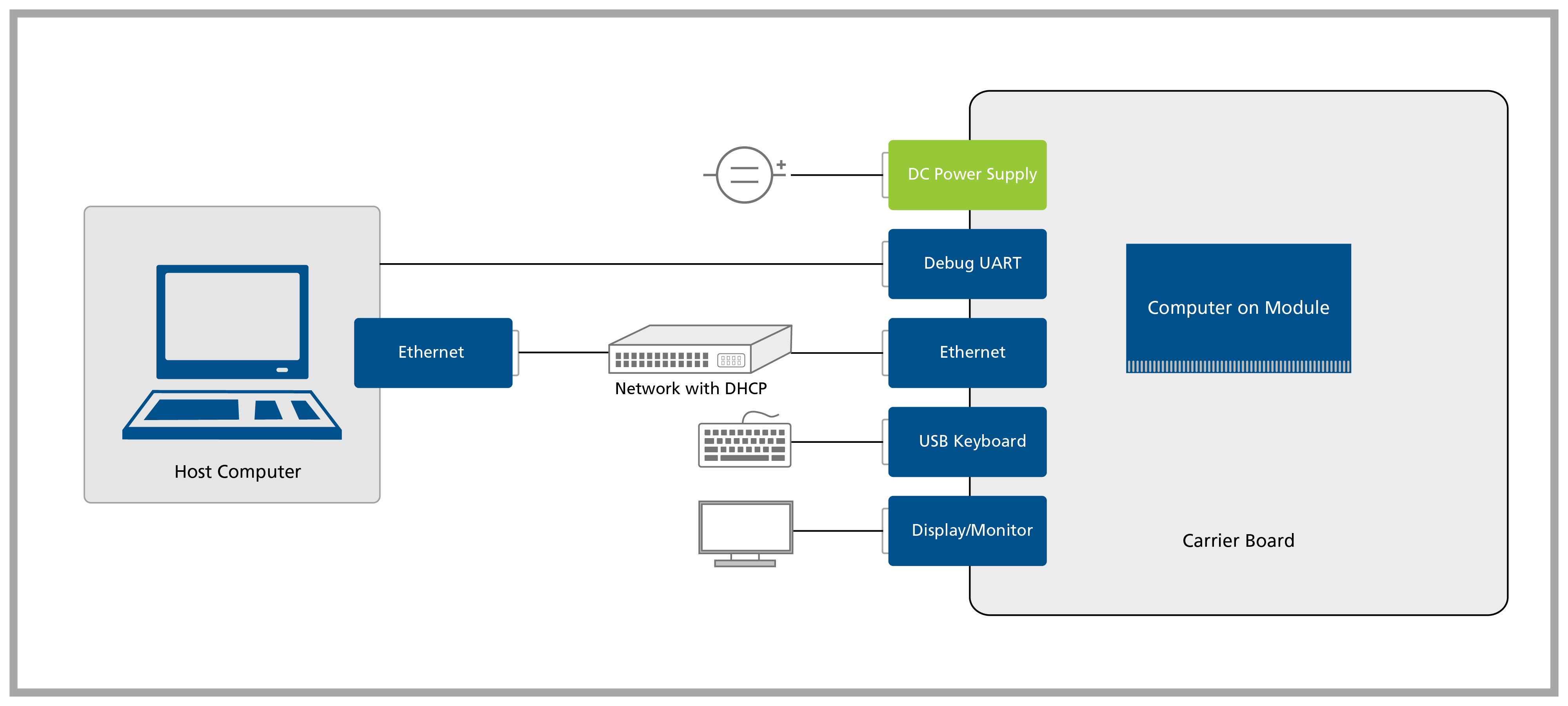
In this first lesson, you will go through the process of unboxing your computer on module and carrier board and assembling the hardware.
A block diagram of the system setup and its connections is presented below for reference.
Prerequisites
| List of required items |
|---|
| Accessory kit: |
| - 12V 30W power supply |
| - USB Type-C to Type-A cable |
| - Ethernet cable |
| USB keyboard and mouse |
| 2x 2.4GHz SMA antennas |
| 2x SMA to MHF4 cables |
| List of recommended items |
|---|
| Verdin Industrial Heatsink |
| HDMI display/monitor |
Step 1
1.1 Remove the Dahlia Carrier Board and the Verdin System on Module from the blisters.
Note that not all modules come with Wi-Fi/Bluetooth connectivity. Check the datasheet of your module for more information.
For more information on how to connect antennas, refer to the article Operating Toradex Wi-Fi/BT Capable Modules Using Dual and Single Antenna Configuration.
1.5 Insert the system on module into the X1 connector of the carrier board as tight as possible, with the module inclined ~30 to 45 degrees in relation to the carrier board.
Verdin Connection Instructions
Follow precautions for handling electrostatic sensitive devices (ESD).
Video Instructions
Step-by-Step Instructions
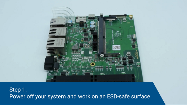
Step 1
Power off your system and work on an ESD-safe surface.
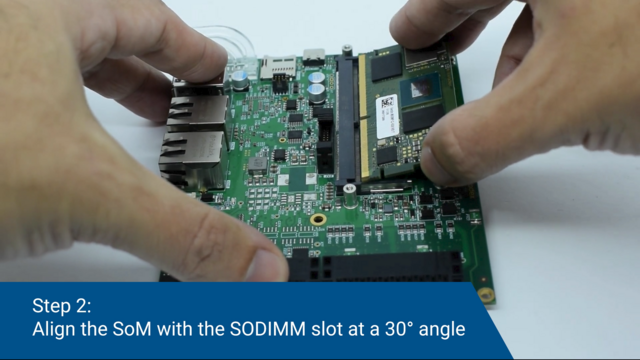
Step 2
Align the SoM with the SODIMM slot at a 30° to 45° angle.
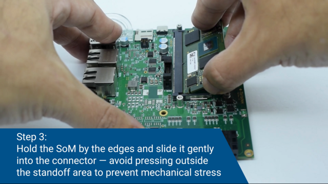
Step 3
Hold the SoM by the edges and slide it gently into the connector — avoid pressing outside the standoff area to prevent mechanical stress.
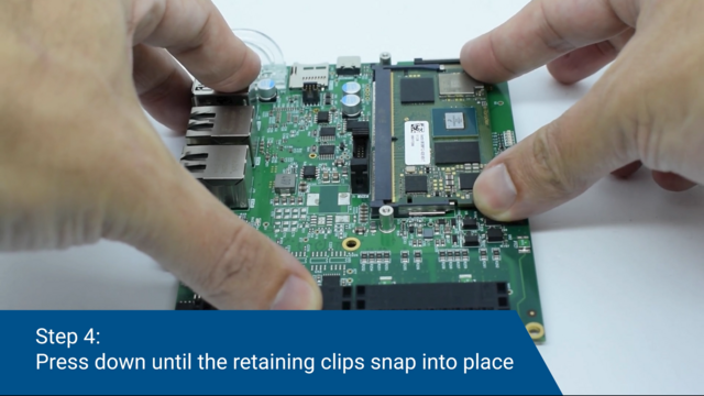
Step 4
Press down until the retaining clips snap into place.
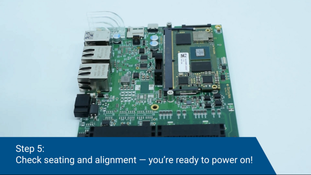
Step 5
Check seating and alignment — you're ready to power on!
Some rare cases with specific combinations of HW require pressing retaining clips until engaging to the module. For these cases, refer to the following steps.
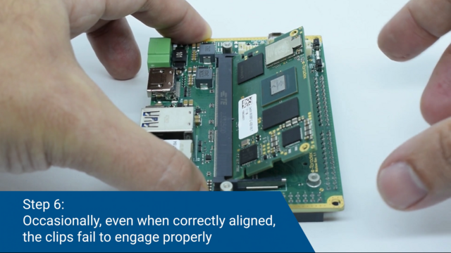
Step 6 (Optional)
Occasionally, even when correctly aligned, the clips fail to engage properly.
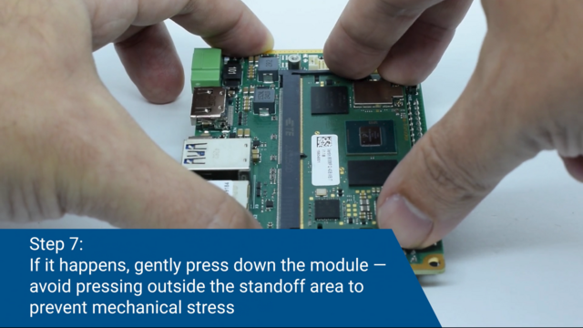
Step 7 (Optional)
If it happens, gently press down the module — avoid pressing outside the standoff area to prevent mechanical stress.
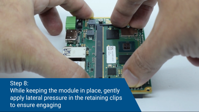
Step 8 (Optional)
While keeping the module in place, gently apply lateral pressure in the retaining clips to ensure engaging.
1.6 Check the module's connection to the carrier board and make sure it is well-connected. The image below has some checkpoints highlighted.
Step 2
Connect the Verdin DSI to HDMI Adapter to the X17 connector of the carrier board. Fixate it by screwing the four included screws.
A Note About MIPI DSI and HDMI on Verdin Computer on Modules
According to the Verdin Family Specification, the MIPI DSI and the HDMI interfaces are exposed on reserved pins. This means that if they are available, they will always be exposed on fixed, predefined pins, on the Verdin SODIMM edge connector.
Note that not all Verdin SoMs are guaranteed to have either interface.
The MIPI DSI is the primary display interface while the HDMI is the secondary display interface. Therefore, in this Quickstart Guide, we use HDMI through the DSI to HDMI adapter when MIPI DSI is available, even if native HDMI is present as well.
Step 3 (Optional)
Please note down the module serial number before attaching the Heatsink — it’s the easiest way to connect via SSH later!
Screw the Verdin Industrial Heatsink on top of the SoM, using the screws that come with it:

Step 4
4.1 Plug an HDMI display into the DSI to HDMI adapter.
4.2 Plug a USB keyboard/mouse into the Dahlia's X4 connector.
4.3 Plug the Ethernet cable into the Dahlia's X11 connector.
Ethernet network must provide DHCP and Internet to the module.
4.4 Plug a USB Type-C to Type-A cable into X3 connector if you want to enter Recovery Mode and load the Toradex Easy Installer.
4.5 Plug the power supply into the Dahlia's barrel jack X9.
Double-check that your power supply is within the rating board limits (7-27V for the X15 connector or 12V for the X17 connector) and that the polarity is not reversed. Also, ensure the power supply's current capacity is sufficient, or the system may shut down unexpectedly. For evaluation purposes, a 12V 2A power supply is recommended.