First Steps with Arducam CSI Camera Module 5MP OV5640 (Torizon)
Introduction
This article provides information on how to start working with the CSI Camera Module based on the OV5640 image sensor from Arducam on Torizon OS.
The scope of this article is specific to the Arducam OV5640. For more information on how cameras work on Torizon OS in general, container permissions, bind mounts, GStreamer pipeline structure, and OpenCV examples, refer to How to use Cameras on Torizon.
The following topics will be covered:
Features
The OV5640 is a high-performance CMOS image sensor designed for a wide range of imaging applications. It offers a combination of high resolution, advanced imaging features, and versatility, making it a popular choice for mobile and embedded camera systems.
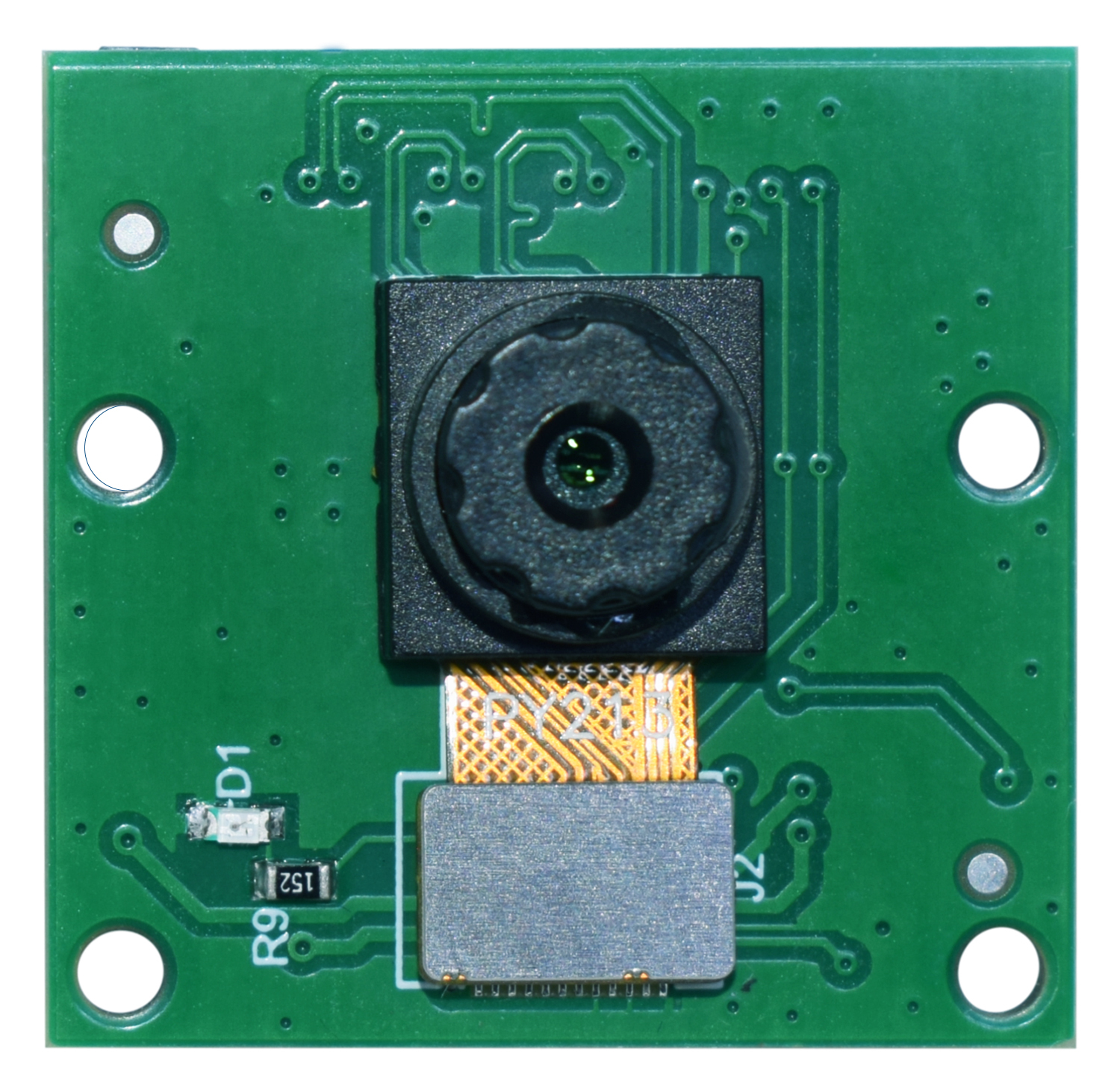
Arducam has designed the OV5640 camera module and integrated it into the Toradex carrier boards via the MIPI protocol. The camera circuit board, after being improved by the Arducam technical team, has reached a mini size of 24x25mm, which makes it easier for visual projects to be applied in narrow spaces with limited size.
Sensor Features:
- Image Sensor: OV5640 from OmniVision
- Still Resolution: 5 Megapixels
- Interface: MIPI CSI-2
- Output Format: 8-/10-bit RGB RAW, RGB, YUV, JPEG
- Max Pixel Array: 2592 x 1944 pixels
- Sensor Image Area: 6.287mm x 4.712mm (7.9mm diagonal)
- Pixel Size: 1.4μm x 1.4μm
- Optical Size: 1/4"
Lens Features:
- IR Sensitivity: Integral IR-cut Filter, visible light only
- Focal length: 4.22mm
- Aperture: F2.0 ±5%
- Field of View (FOV): 84.2°(D)×71.7°(H)×57°(V)
- Lens Mount: Stock Lens
Datasheets
Arducam CSI Camera Module OV5640 Datasheet
Compatible Products
Hardware
The Arducam CSI Camera Module 5MP OV5640 is sold together with a flat connector cable.
The following Toradex carrier boards support the MIPI CSI-2 interface and are compatible with the camera kit out of the box:
This camera module is supported for the following SoMs:
Software
Torizon OS includes the OV5640 device tree overlays, already pre-built inside the image.
To enable the camera, you need to activate the required overlay and bring up a containerized GStreamer pipeline, as shown in the Camera Usage section.
Hardware Setup
What I need to order
You can have the Arducam OV5640 CSI Camera Module working with specific Toradex computers on modules and carrier boards. See the compatible products.
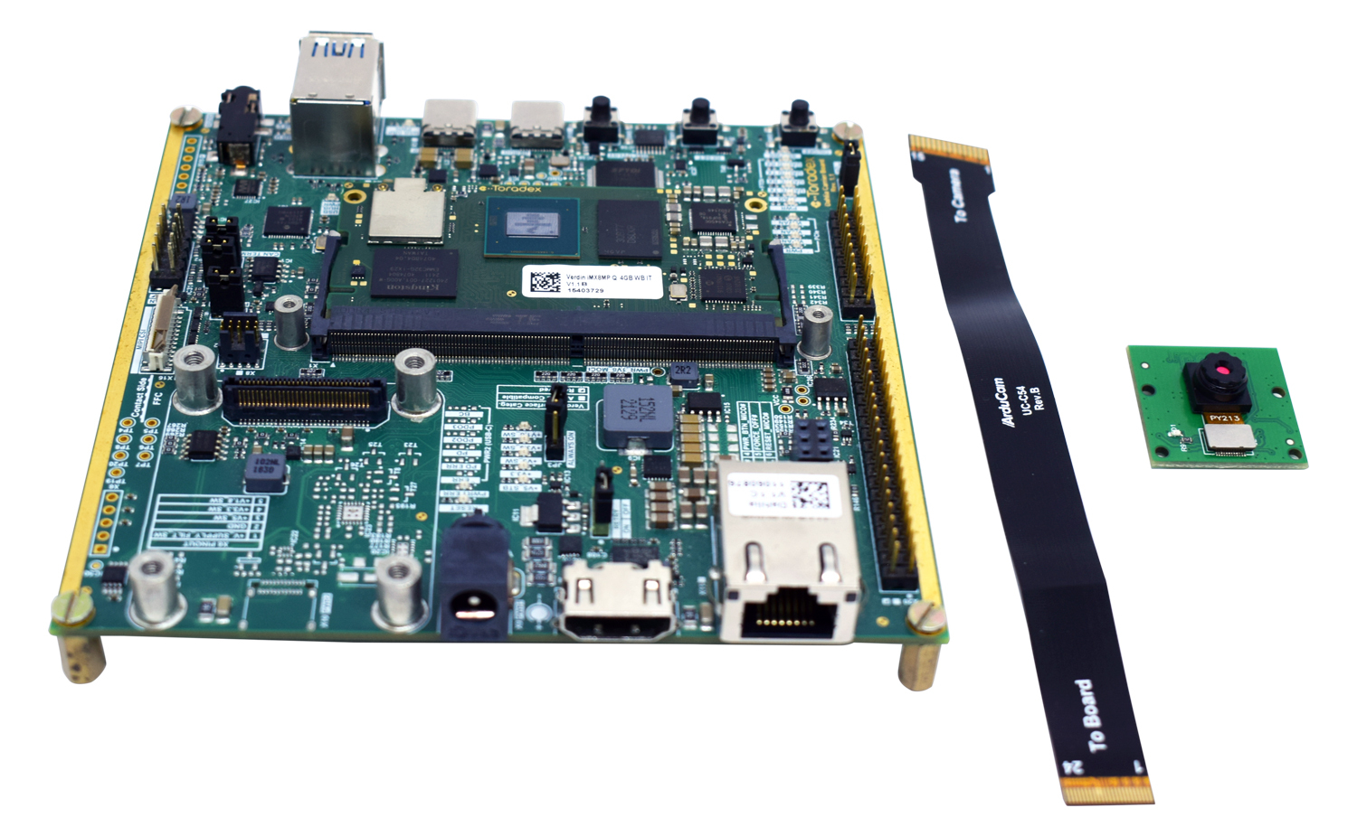
Besides the Module and the Carrier Board, you will need to order:
- The Arducam OV5640 Camera Module;
- The flat cable for connecting the Camera Module to the Carrier Board.
Where do I order
You can order the Toradex computer on Modules and the carrier boards online in the Toradex Webshop.
You can order the Arducam Camera Module and the needed accessories on the Arducam Shop.
Please refer to the instructions below for connecting the camera module to your specific carrier board.
Cable Connection
Connect the flat cable to the camera module as shown in the following pictures:
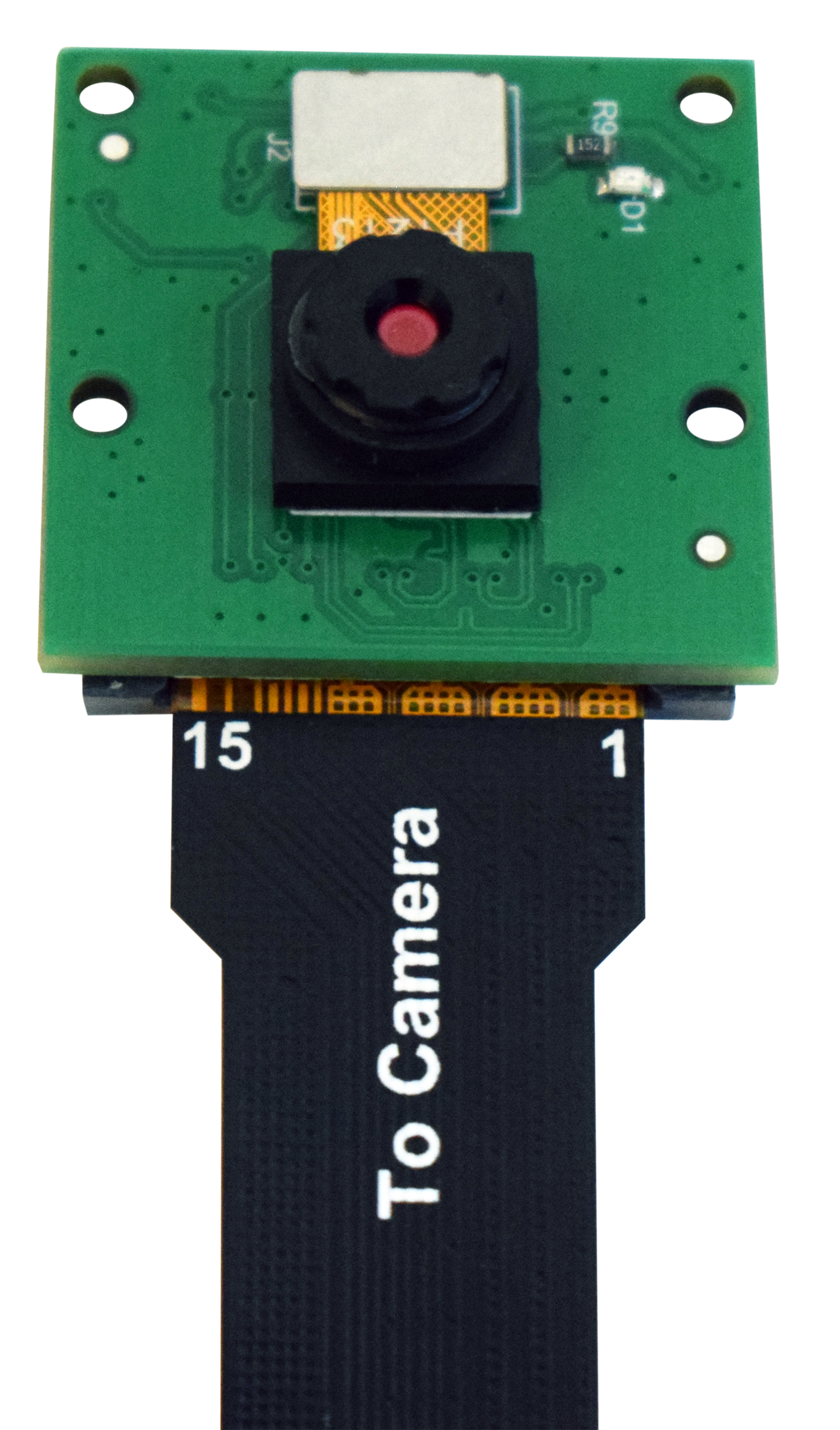
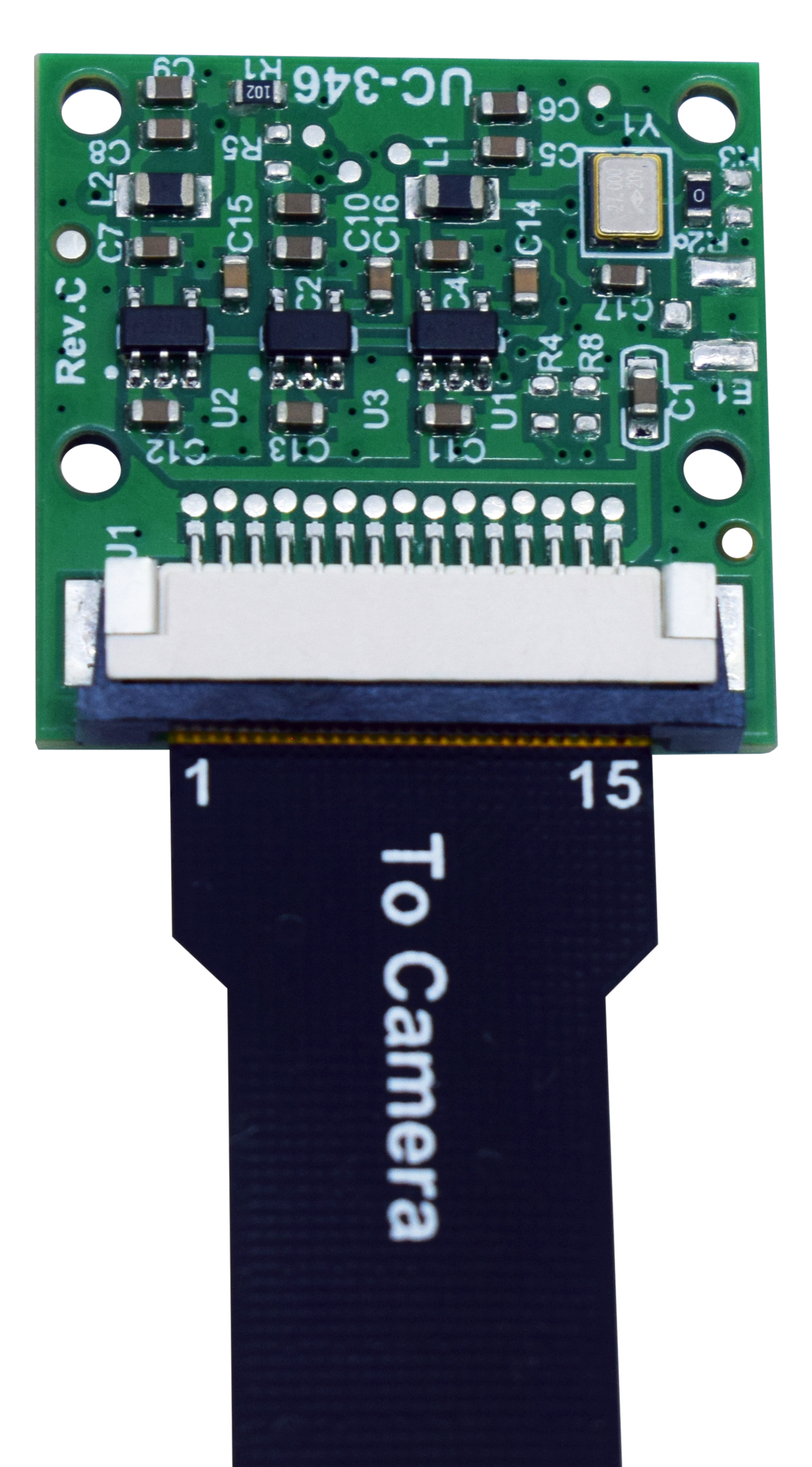
Please disconnect any power and USB cables from the board before connecting the flat cable to the MIPI-CSI bus to avoid any damage to the camera!
Connection to Dahlia Carrier Board
Connect the camera to the Dahlia Carrier Board, assuring that the flat cable contacts are on the correct side, as indicated in the figures below.
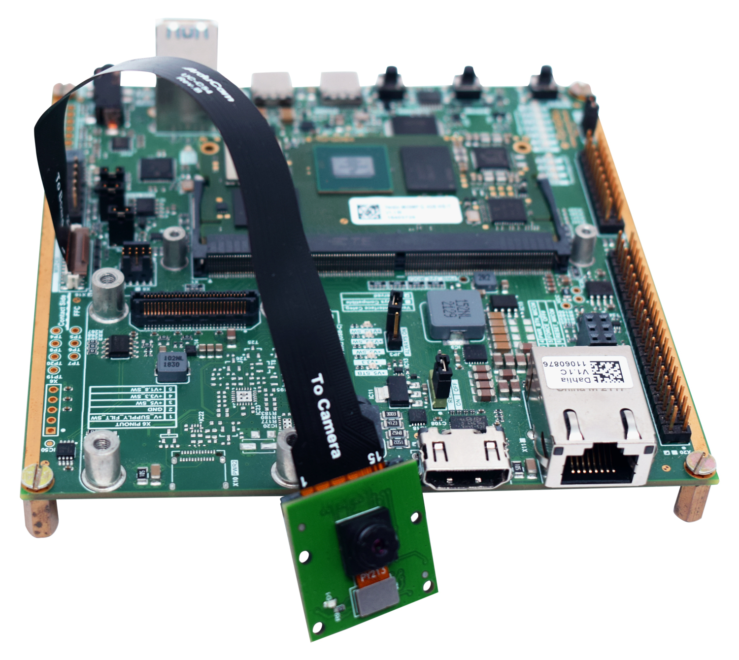
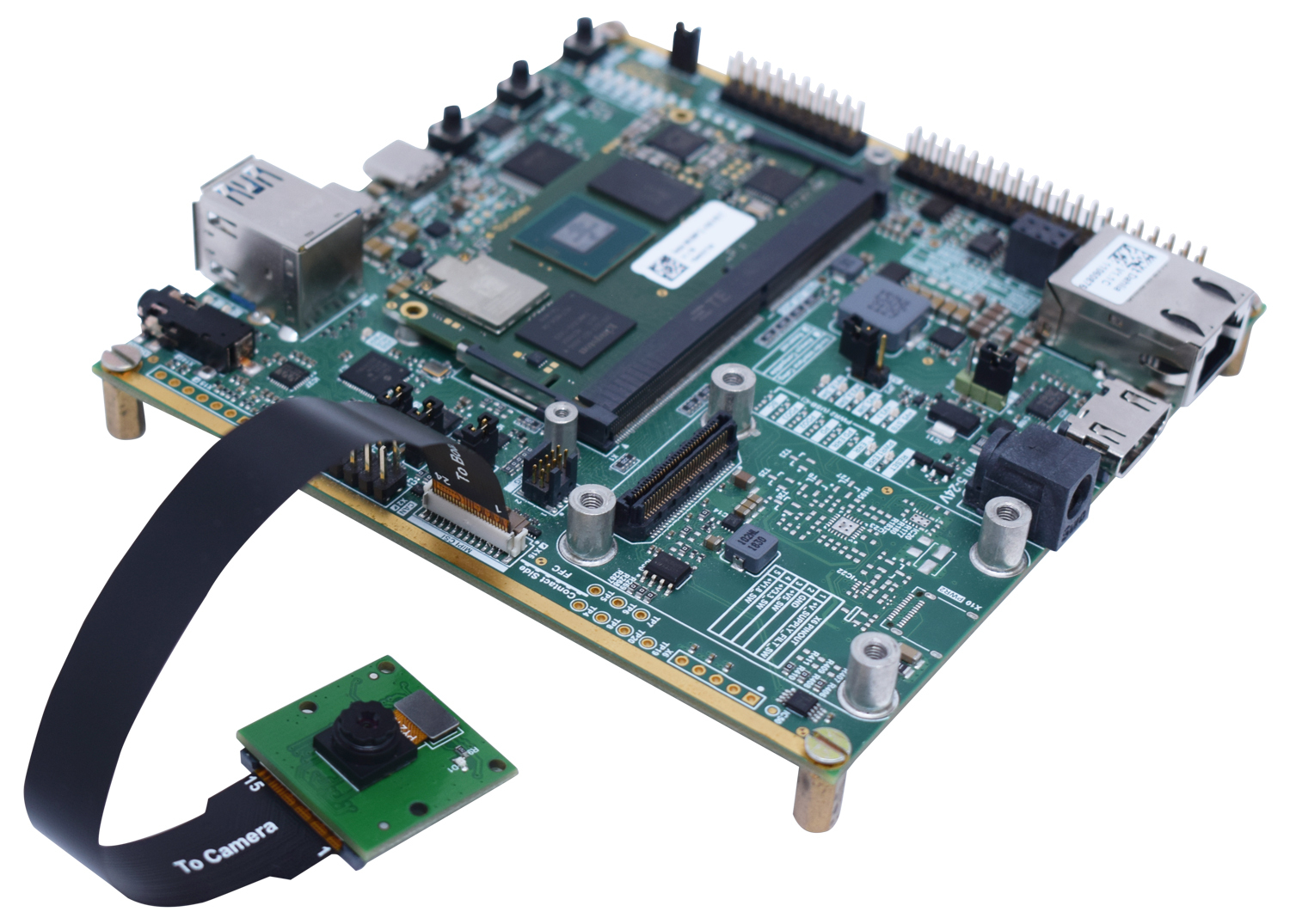
- For the Dahlia Carrier Board, the MIPI-CSI Camera interface is on connector X16.
Connection to Mallow Carrier Board
Connect the camera to the Mallow Carrier Board, assuring that the flat cable contacts are on the correct side, as indicated in the figures below.
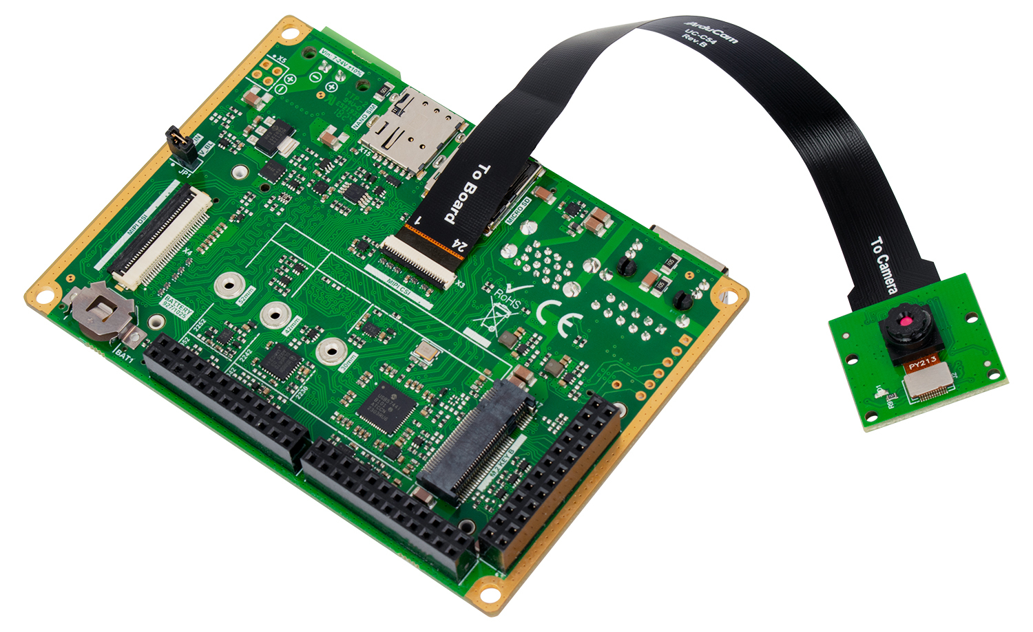
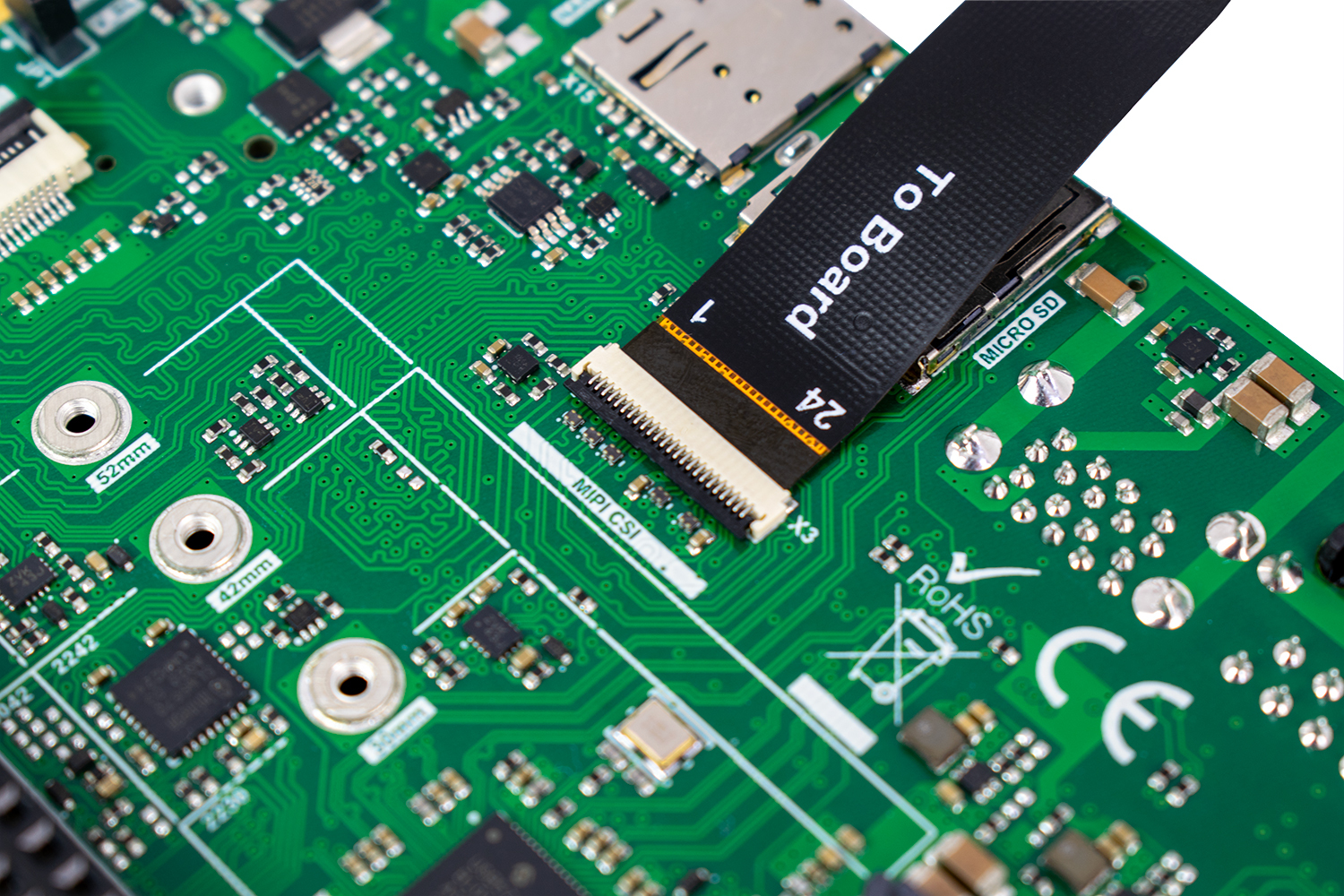
- For the Mallow Carrier Board, the MIPI-CSI Camera interface is on connector X3.
Connection to Ixora Carrier Board
Connect the camera to the Ixora Carrier Board, assuring that the flat cable contacts are on the correct side, as indicated in the figures below.
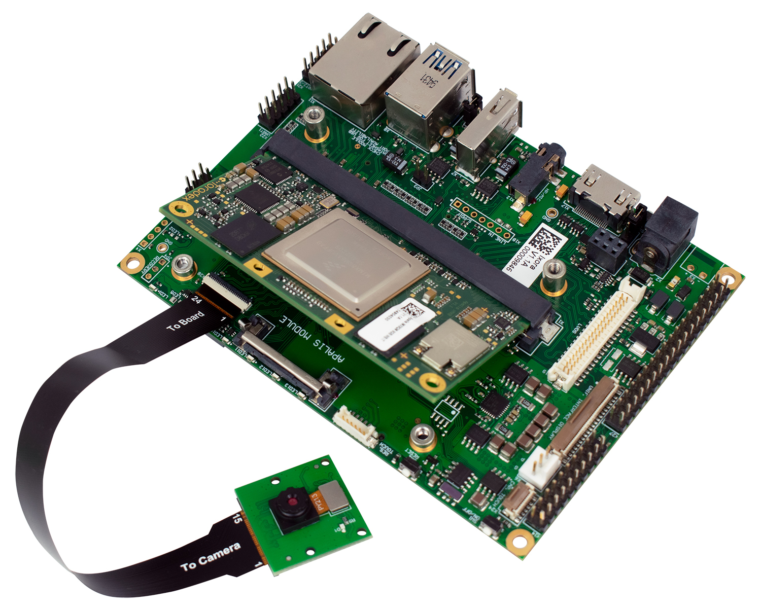
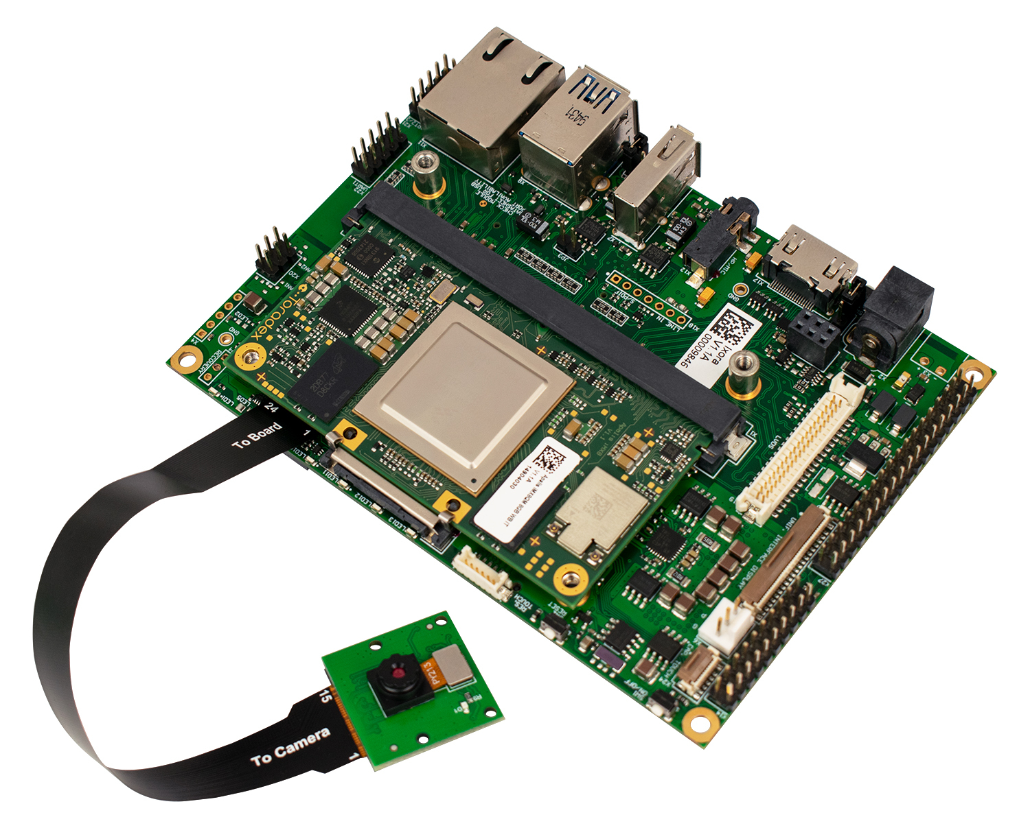
- For the Ixora Carrier Board, the MIPI-CSI Camera interface is on connector X28.
Connection to Verdin Development Board
Connect the camera to the Verdin Development Board, assuring that the flat cable contacts are on the correct side, as indicated in the figures below:
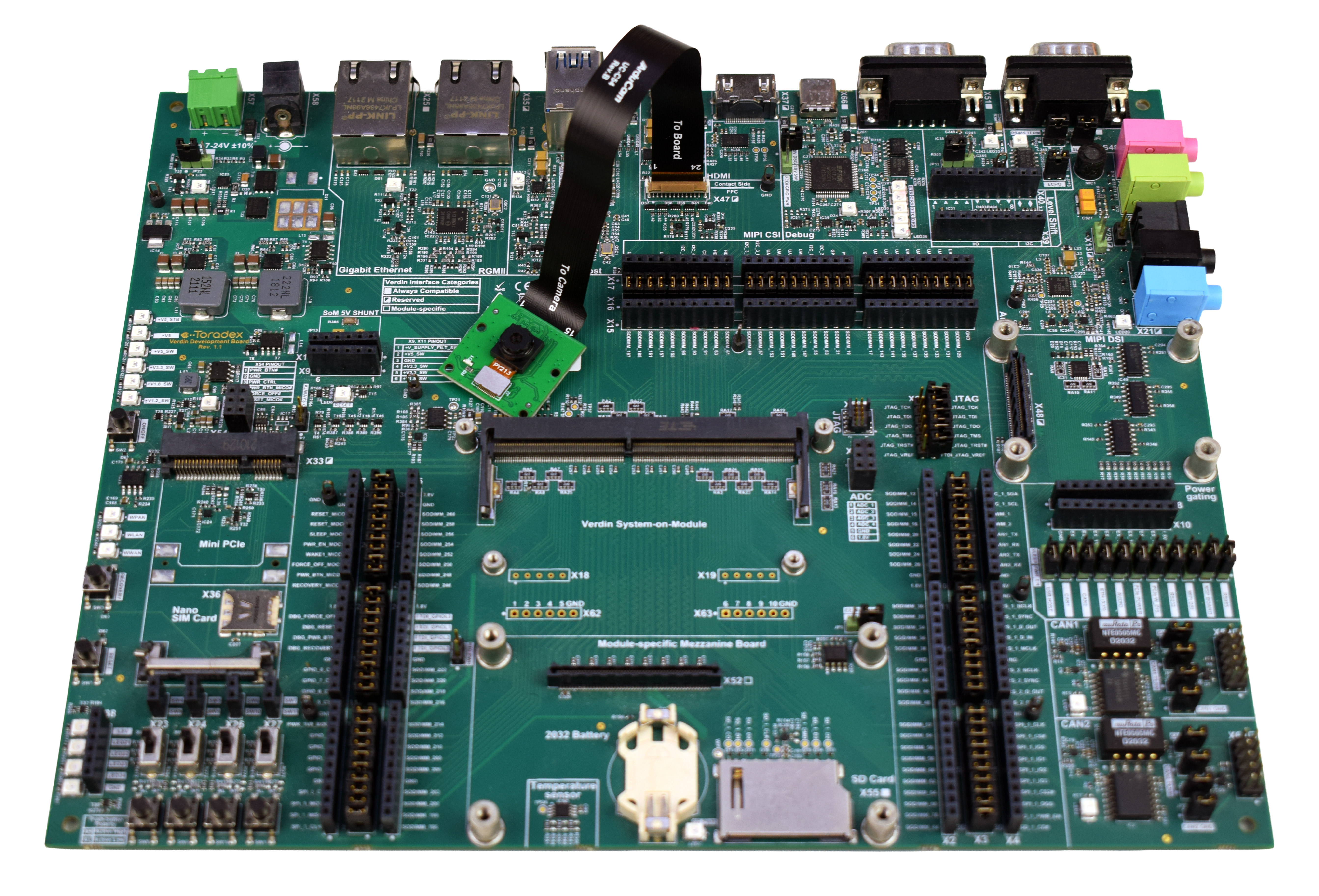
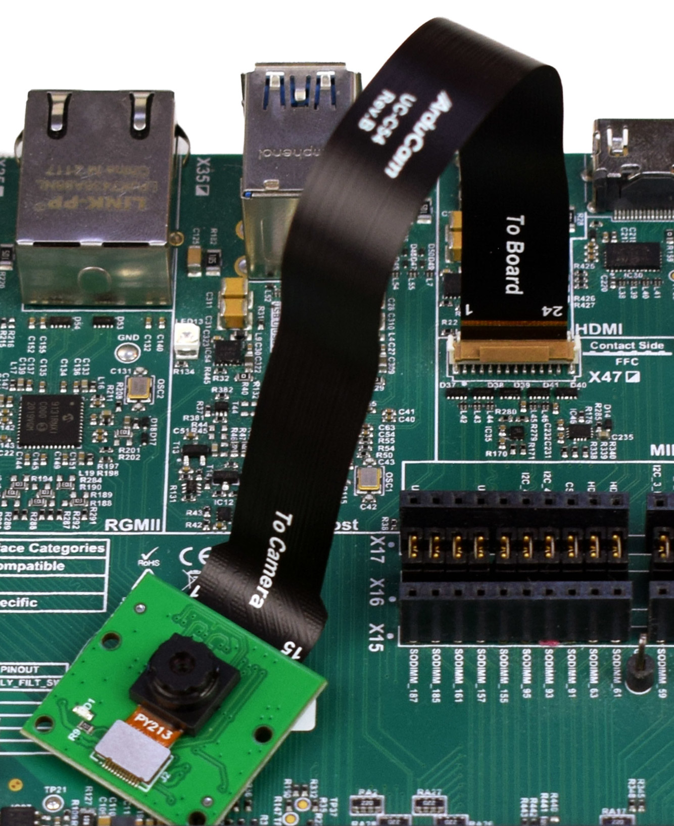
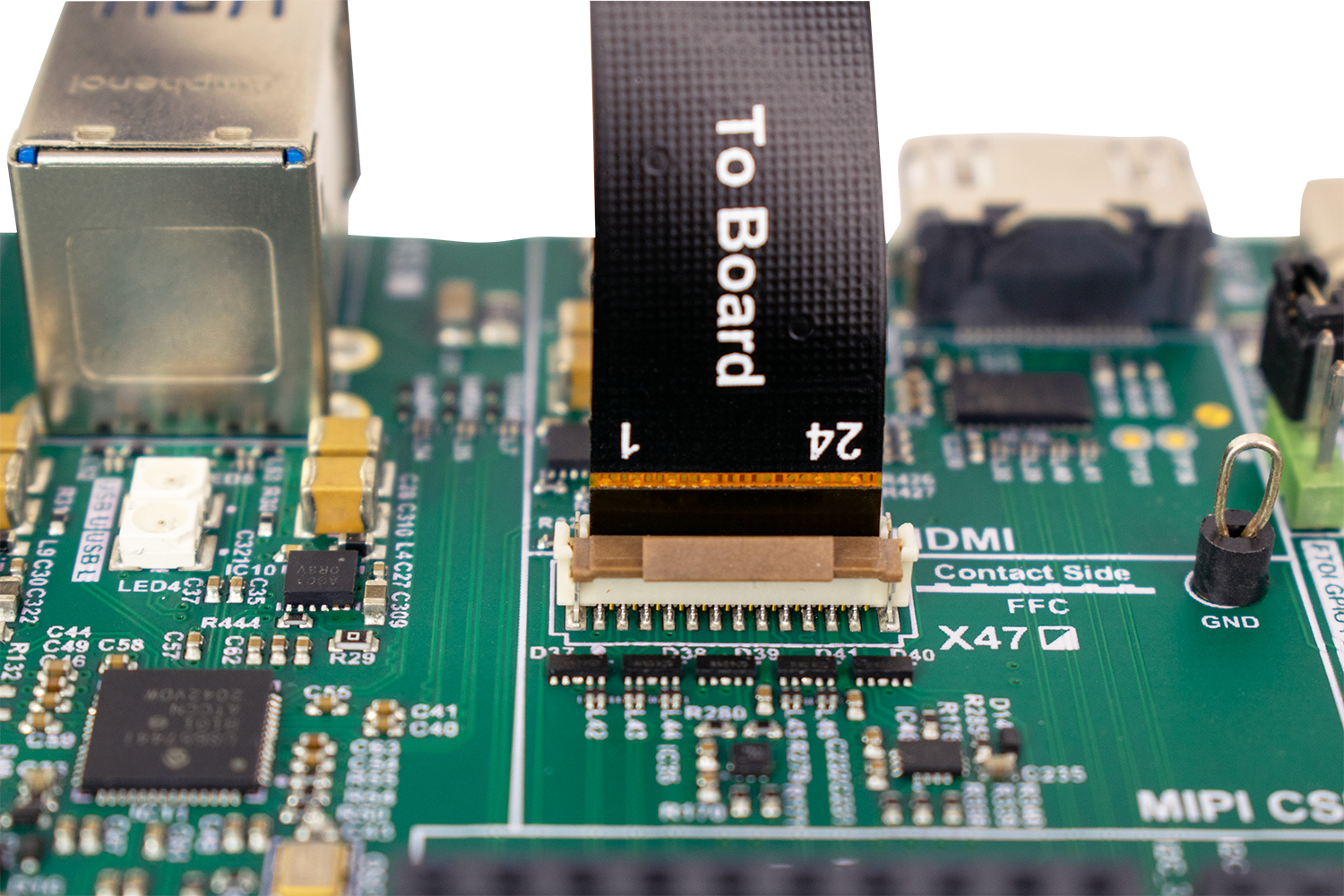
- For the Verdin Development Board, the MIPI-CSI Camera interface is on connector X47.
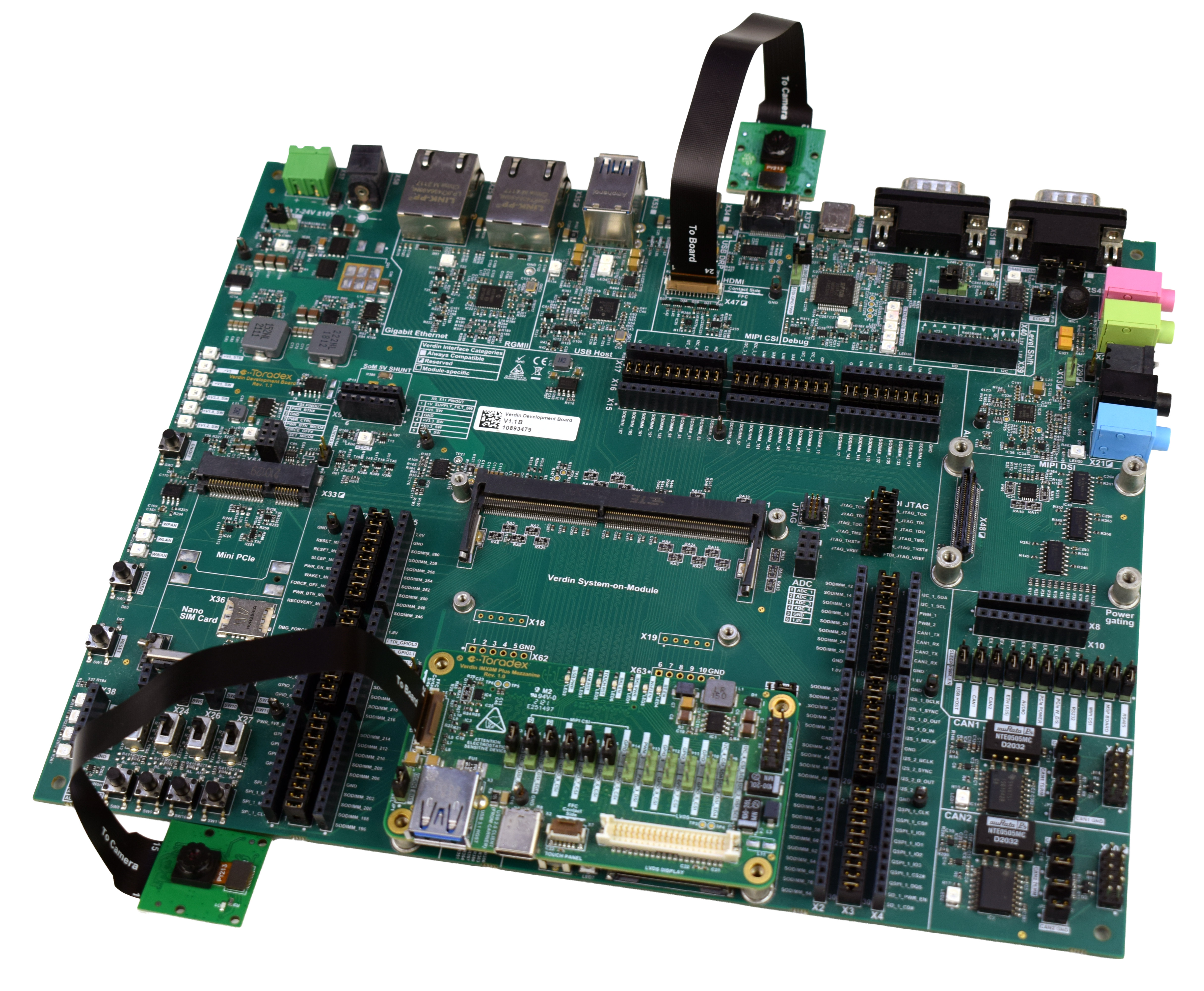
Connection to Mezzanine and Dual-Camera Setup
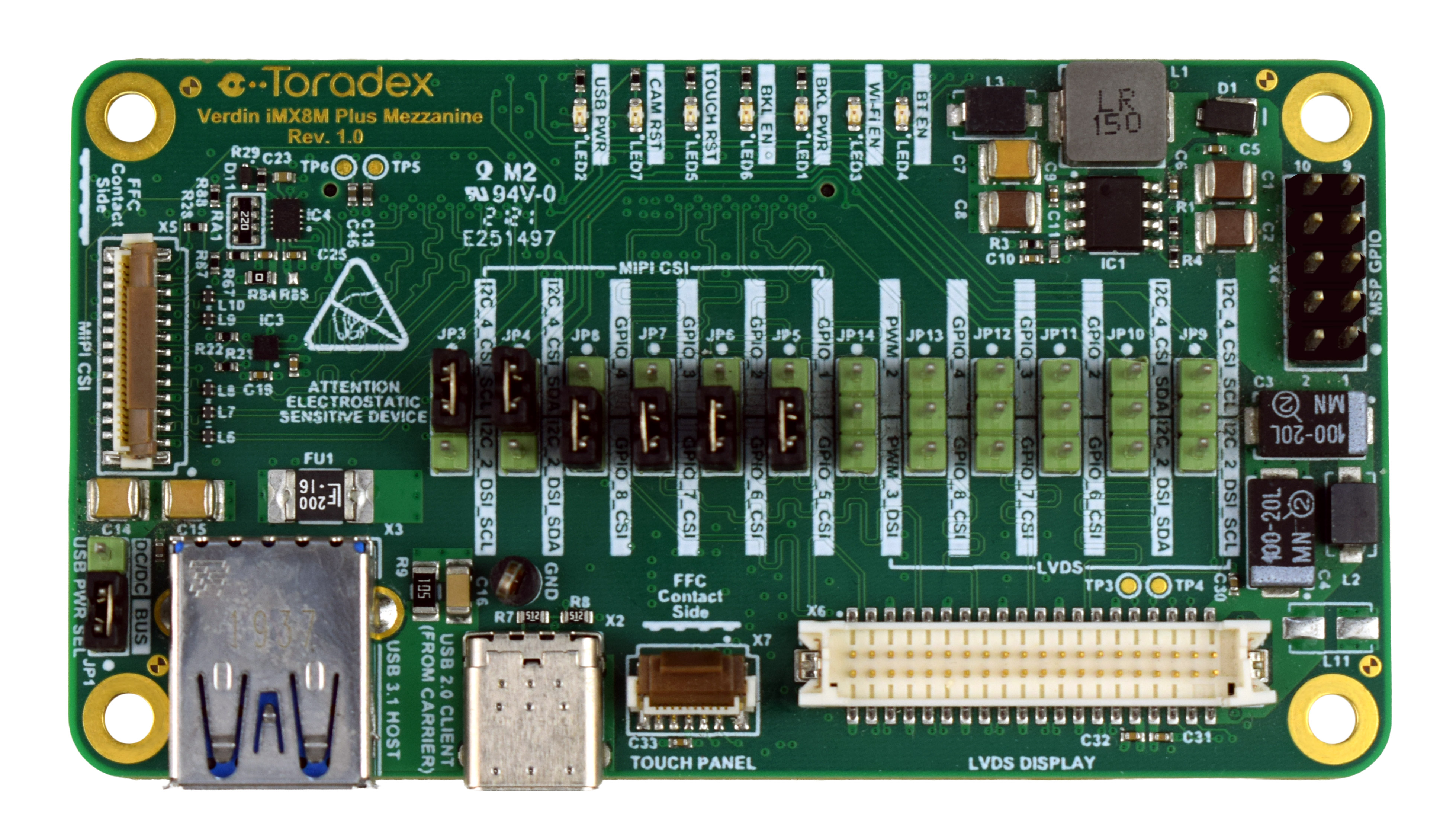
The Verdin iMX8M Plus Mezzanine is an add-on board that mounts on the Verdin Development Board and exposes a second MIPI-CSI connector (X5). You can connect a camera to the mezzanine port on its own, or alongside the native carrier board port for a dual-camera setup.
Connecting the Camera to the Mezzanine
Connect the camera to the mezzanine as indicated in the figures below:
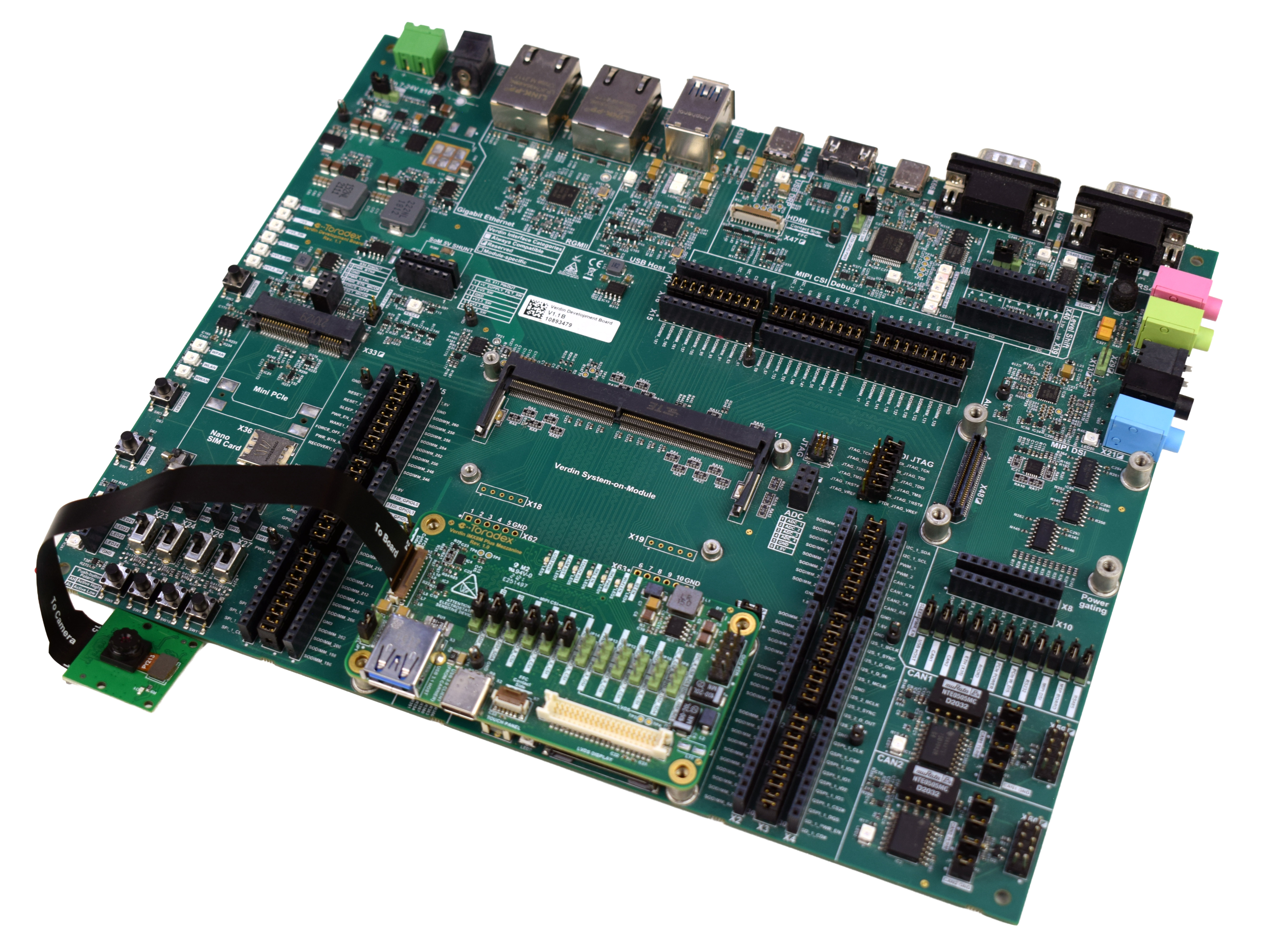
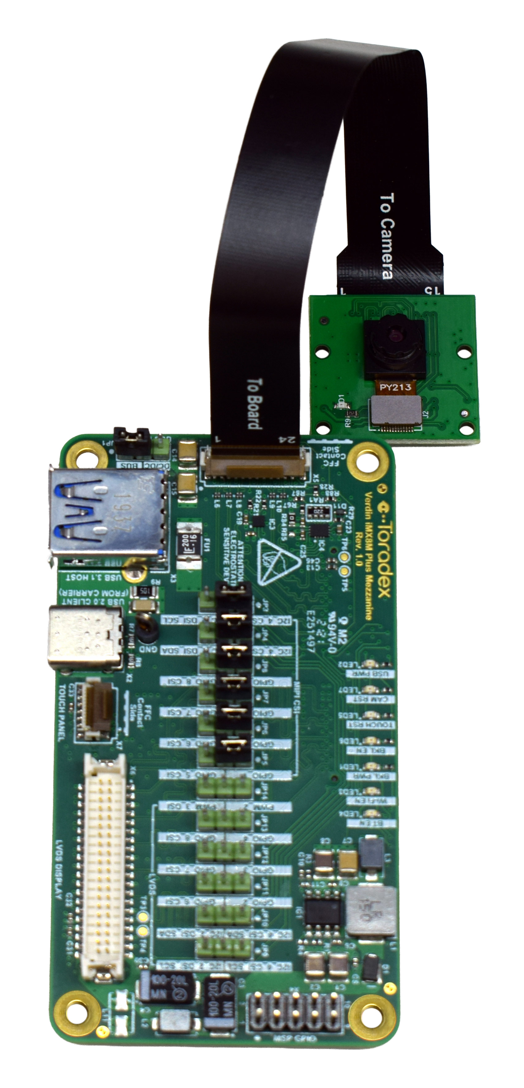
- The mezzanine MIPI-CSI Camera interface is on connector X5.
Mezzanine Jumper Configuration
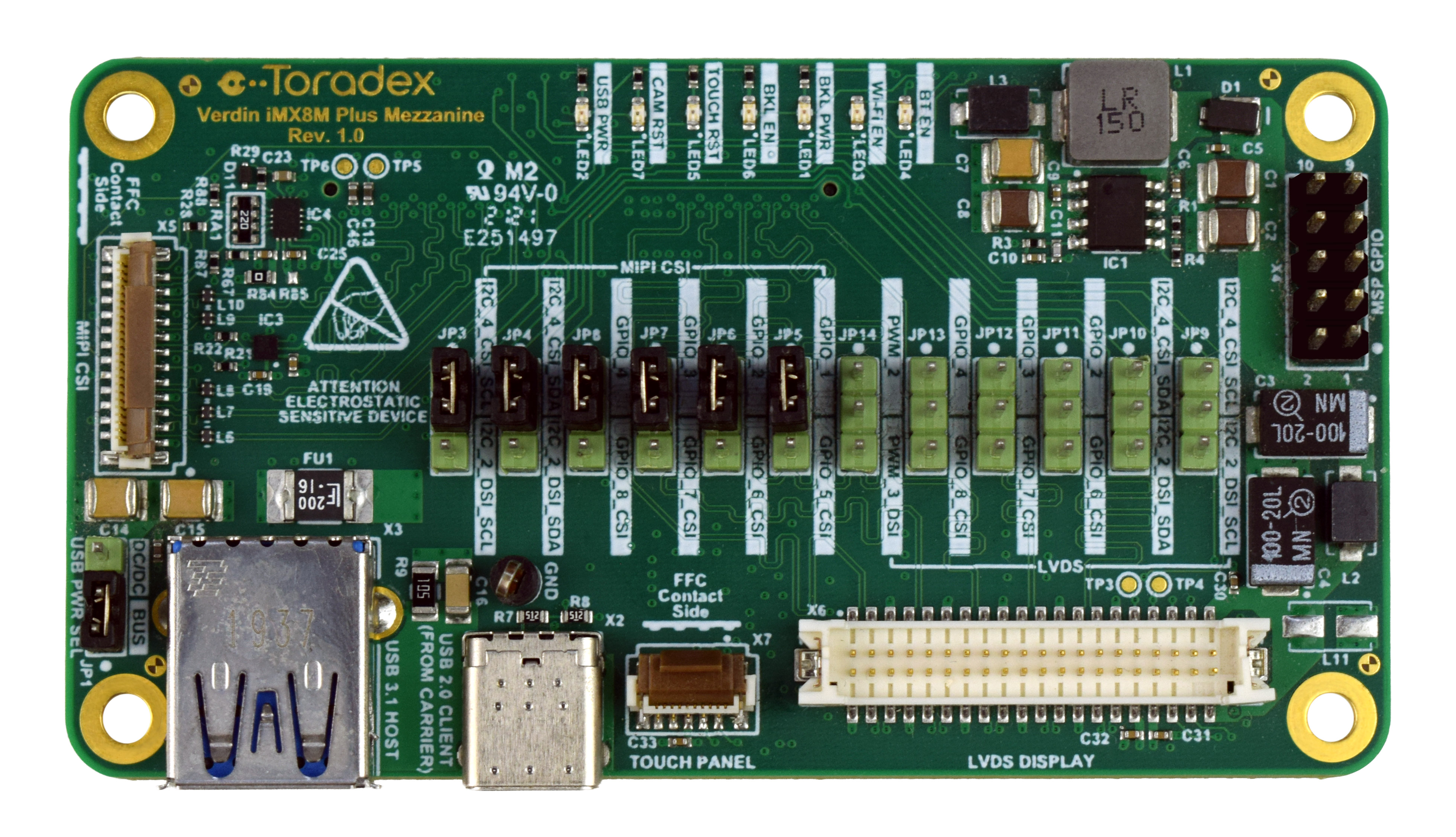
The mezzanine includes jumpers on the MIPI-CSI interface that must be configured according to the intended use:
- Default: use this position when operating the mezzanine camera port alone.
- Alternate: use this position when using the mezzanine together with the native carrier board port simultaneously.
Dual-Camera Setup
To use both cameras simultaneously, connect one camera to the native CSI connector (X47) and the other to the mezzanine connector (X5), and make sure the mezzanine jumper is set to the Alternate position.
The flat cable (used to connect the carrier board and the camera adaptor) is fragile. If your camera does not work, make sure to test the cable connections on the flat cable.
Camera Usage
This article covers three possible configurations for using the camera:
- Native port only: connect the camera directly to the native MIPI-CSI port on the carrier board.
- Mezzanine only: connect the camera to the mezzanine port, with the jumper in either Default or Alternate position.
- Native + Mezzanine: for dual camera support using both ports simultaneously, with the mezzanine jumper set to Alternate.
For hardware setup and jumper configuration of the mezzanine, see the Connection to Mezzanine section.
On the Verdin iMX8M Plus, the horizontal resolution is limited to 2048 pixels in either of the following configurations:
- Both MIPI CSI-2 interfaces are used simultaneously.
- The camera is connected to the mezzanine port, even when the native port is not in use.
We recommend using a display to be able to visualize the captured image during camera testing.
Connect to the SoM
After completing the hardware setup for your intended configuration, connect to the device via SSH or a serial terminal.
Apply the Device Tree Overlay
On Torizon OS there are two ways to apply the overlay required to enable the camera:
- Approach 1—Development / Production: build a customized Torizon OS image with TorizonCore Builder.
- Approach 2—Evaluation / Prototyping: edit
overlays.txtdirectly on the device. Fastest path to verify the camera works.
For more background on overlays in Torizon OS, see Device Tree Overlays on Torizon.
Approach 1: Using TorizonCore Builder
For development and production workflows, the recommended method is to bake the overlay into a custom Torizon OS image with TorizonCore Builder.
Prerequisites:
Step 1—Get a base Torizon OS image
Place the .tar file for the desired Torizon OS image in your TorizonCore Builder working directory.
You can get this image in two ways:
- Download it manually:
Grab a Torizon OS 7 image for your SoM from the Toradex Download Links page, and save the .tar in your working directory.
- Pull it from a running board:
If a board already runs Torizon OS, point TorizonCore Builder at it over SSH and let it fetch the matching image:
$ torizoncore-builder images download --remote-host <board-ip> --remote-username <user> --remote-password <password>
This reads the version from the device and downloads the matching image into your working directory.
Step 2—Clone the kernel and overlays repositories
These two repositories supply the device tree sources and the overlay sources. The branch must match your Torizon OS version. Adjust the branch name if you are on a different release.
$ git clone -b toradex_6.6-2.2.x-imx git://git.toradex.com/linux-toradex.git linux
$ git clone -b toradex_6.6-2.2.x-imx git://git.toradex.com/device-tree-overlays.git device-trees
For other SoM families (for example, AM62/AM62P with the TI kernel), check Device Tree Overlays on Torizon—Clone The Toradex Repositories for the correct branches.
Step 3—Create the tcbuild.yaml
In your working directory, create a tcbuild.yaml file using the template following.
Before building the image, update the following fields:
- Replace
<torizon-os-tar>with the name of the Torizon OS image.tarfile in your working directory. - Replace
<output-image-folder>with the directory where TorizonCore Builder should generate the customized image. - Update the
<base-device-tree>to match your SoM variant and carrier board (see more details following). - Check the overlays.add list provided following and leave uncommented only the overlay sources that match your hardware setup.
input:
  easy-installer:
    local: <torizon-os-tar>.tar

customization:
  device-tree:
    include-dirs:
      - linux/include/
    custom: linux/arch/arm64/boot/dts/freescale/<base-device-tree>.dts
    overlays:
      add:
        # Native port only:
        - device-trees/overlays/verdin-imx8mp_ov5640-27mhz_overlay.dts
        # Mezzanine only (uncomment the one matching your jumper position):
        # - device-trees/overlays/verdin-imx8mp_mezzanine_ov5640-27mhz-default-jumpers_overlay.dts
        # - device-trees/overlays/verdin-imx8mp_mezzanine_ov5640-27mhz-alt-jumpers_overlay.dts
        # Dual camera: use the native overlay above PLUS the mezzanine alternate overlay

output:
  easy-installer:
    local: <output-image-folder>
The custom: field sets the base device tree for your SoM and carrier board. Replace <base-device-tree>.dts with the file that matches your hardware setup.
To find the correct device tree for your setup, search the cloned kernel tree for your SoM:
# For example, for the Verdin i.MX 8M Plus:
$ find linux -name "*imx8mp-verdin*.dts"
This lists the device trees available for that SoM; pick the one whose module variant and carrier board match your setup, for example:
mx8mp-verdin-wifi-dev.dts→ Verdin Development Board with Wi-Fimx8mp-verdin-wifi-dahlia.dts→ Dahlia Carrier Board with Wi-Fimx8mp-verdin-wifi-yavia.dts→ Yavia Carrier Board with Wi-Fimx8mp-verdin-nonwifi-dev.dts→ Verdin Development Board without Wi-Fi
Step 4—Build the custom image
$ torizoncore-builder build
The output image is generated in the directory specified in the tcbuild.yaml created in Step 3.
Step 5—Deploy
Install the custom image on the device using Toradex Easy Installer, through SSH, or via Torizon Cloud. For deploy options and commands, see Deploy The Custom Toradex Easy Installer Image.
Approach 2: Enabling the Overlay on the Device
The overlays required to enable the Arducam OV5640 camera are already pre-built and shipped inside the Torizon OS image. The fastest way to evaluate the camera is to add them to the overlays.txt file on the device.
Step 1—Find the active OSTree deployment
Get the <HASH> value of the current OSTree deployment with:
# cat /proc/cmdline
Look for the ostree=/ostree/boot.X/torizon/<HASH>/0 substring in the output.
Copy the <HASH> value from this path. It is used to locate the overlays.txt file for the active Torizon OS deployment.
Step 2—Edit overlays.txt
Using the <HASH> obtained in the previous step, open the following file with sudo privileges:
/sysroot/boot/ostree/torizon-<HASH>/dtb/overlays.txt
Then, select the tab that matches your intended camera configuration and append the indicated overlays to the fdt_overlays variable.
Append the native overlay for your SoM:
- Verdin Family SoMs:
verdin-[SoM name]_ov5640-27mhz_overlay.dtbo - Apalis iMX8:
apalis-imx8_ov5640-27mhz_overlay.dtbo
Example for Verdin iMX8MP, preserving default pre-enabled overlays:
fdt_overlays=verdin-imx8mp_hdmi_overlay.dtbo verdin-imx8mp_dsi-to-hdmi_overlay.dtbo verdin-imx8mp_ov5640-27mhz_overlay.dtbo
Jumper configuration: the jumper can be set to either Default or Alternate (see the Connection to Mezzanine section). The functional result is the same in both cases; only the overlay name differs.
Resolution limit: on the Verdin iMX8M Plus, the mezzanine port is limited to a maximum horizontal resolution of 2048 pixels.
Append the mezzanine overlay that matches your jumper position:
- Jumper Default:
verdin-[SoM name]_mezzanine_ov5640-27mhz-default-jumpers_overlay.dtbo - Jumper Alternate:
verdin-[SoM name]_mezzanine_ov5640-27mhz-alt-jumpers_overlay.dtbo
Example for Verdin iMX8MP with jumper in Default position:
fdt_overlays=verdin-imx8mp_hdmi_overlay.dtbo verdin-imx8mp_dsi-to-hdmi_overlay.dtbo verdin-imx8mp_spidev_overlay.dtbo verdin-imx8mp_mezzanine_ov5640-27mhz-default-jumpers_overlay.dtbo
Jumper configuration: the jumper must be set to Alternate (see the Connection to Mezzanine section).
Resolution limit: on the Verdin iMX8M Plus, both cameras are limited to a maximum horizontal resolution of 2048 pixels while using the Dual Camera setup.
Append both overlays, the native overlay for your SoM and the mezzanine alternate overlay:
- Native (Verdin Family):
verdin-[SoM name]_ov5640-27mhz_overlay.dtbo - Native (Apalis iMX8):
apalis-imx8_ov5640-27mhz_overlay.dtbo - Mezzanine Alternate:
verdin-[SoM name]_mezzanine_ov5640-27mhz-alt-jumpers_overlay.dtbo
Example for Verdin iMX8MP:
fdt_overlays=verdin-imx8mp_hdmi_overlay.dtbo verdin-imx8mp_dsi-to-hdmi_overlay.dtbo verdin-imx8mp_spidev_overlay.dtbo verdin-imx8mp_ov5640-27mhz_overlay.dtbo verdin-imx8mp_mezzanine_ov5640-27mhz-alt-jumpers_overlay.dtbo
Step 3—Sync and Reboot
# sync
# sudo reboot
Step 4—Verify
After reboot, confirm that the overlays were applied successfully:
# ls /proc/device-tree/chosen/overlays/
# cat /proc/device-tree/chosen/overlays/verdin-imx8mp_ov5640-27mhz_overlay.dtbo
A value of 0 indicates the overlay was applied successfully. For details on this verification, see Checking applied overlays.
If an overlay change prevents the kernel from booting, after a few failed attempts (3 by default) Torizon OS automatically rolls back to the previous deployment. See Update Rollbacks.
Set Up the Container Environment
Running camera applications on Torizon OS requires at least two containers:
- A Weston container, providing the Wayland compositor to display the video output.
- A GStreamer + V4L2 container, running the pipeline that captures from the camera.
For background on container permissions, bind mounts and GUI containers, refer to Camera usage with containers.
Before launching any containers, stop any other containers that might be running on your device:
# docker stop $(docker ps -a -q)
Build the GStreamer Container
The torizon-samples repository provides a Dockerfile for a GStreamer + V4L2 container. Clone the repository and build the image on your host computer, then push it to your Docker Hub account.
Make sure you have configured your build environment for Torizon containers before running docker build.
$ git clone --branch bookworm https://github.com/toradex/torizon-samples.git
$ cd torizon-samples/gstreamer/bash/simple-pipeline
Since the container image needs to target linux/arm64/v8, you need to enable ARM emulation on your host machine before building. This allows an x86 host to build images for ARM64 transparently.
Run the following command on your host machine:
$ docker run --rm -it --privileged torizon/binfmt
ARM emulation is registered at the kernel level and persists until the host machine is rebooted. Re-run the command preceding after any host reboot.
Then build the image according to your SoM family, replacing <your-dockerhub-username> with your own:
$ docker build --build-arg BASE_NAME=wayland-base-vivante \
    --build-arg IMAGE_ARCH=linux/arm64/v8 \
    -t <your-dockerhub-username>/gst_example .
$ docker build --build-arg BASE_NAME=wayland-base-am62 \
    --build-arg IMAGE_ARCH=linux/arm64/v8 \
    --build-arg IMAGE_TAG=3 \
    -t <your-dockerhub-username>/gst_example .
After the build completes, push the image to your Docker Hub account:
$ docker push <your-dockerhub-username>/gst_example
For more details about the Dockerfile, refer to How to use GStreamer on Torizon OS.
Launch the Weston Container
On the target board, launch the Weston container according to your SoM family:
# docker container run -d --name=weston --net=host \
    --cap-add CAP_SYS_TTY_CONFIG \
    -v /dev:/dev -v /tmp:/tmp -v /run/udev/:/run/udev/ \
    --device-cgroup-rule="c 4:* rmw" --device-cgroup-rule="c 253:* rmw" \
    --device-cgroup-rule="c 13:* rmw" --device-cgroup-rule="c 226:* rmw" \
    --device-cgroup-rule="c 10:223 rmw" --device-cgroup-rule="c 199:0 rmw" \
    torizon/weston-imx8:4 \
    --developer
# docker container run -d --name=weston --net=host \
    --cap-add CAP_SYS_TTY_CONFIG \
    -v /dev:/dev -v /tmp:/tmp -v /run/udev/:/run/udev/ \
    --device-cgroup-rule="c 4:* rmw" --device-cgroup-rule="c 253:* rmw" \
    --device-cgroup-rule="c 13:* rmw" --device-cgroup-rule="c 226:* rmw" \
    --device-cgroup-rule="c 10:223 rmw" \
    torizon/weston-am62:4 \
    --developer
To learn more about the device-cgroup-rule options used preceding, refer to the Hardware Access through Control Group Rules (cgroup) section of the Torizon Best Practices Guide.
Find the Capture Device
The OV5640 driver exposes one capture device per active port (/dev/video<N>). The exact node number can vary depending on your SoM and which other devices are present, so the first time you set up the camera it's worth identifying the right node explicitly.
List the video devices on the host:
/dev/video0 /dev/video1 /dev/video2 /dev/video3
Then start the GStreamer container, adjusting the --device flags to include all the /dev/video* nodes listed previously.
Also, remember to input your <your-dockerhub-username>:
# docker run --rm -it -v /tmp:/tmp -v /var/run/dbus:/var/run/dbus -v /dev:/dev -v /sys:/sys \
    --device /dev/video0 --device /dev/video1 --device /dev/video2 --device /dev/video3 \
    --device-cgroup-rule='c 81:* rmw' --device-cgroup-rule='c 199:* rmw' --device-cgroup-rule='c 226:* rmw' \
    --entrypoint '/bin/bash' \
    <your-dockerhub-username>/gst_example
Once inside the container, list and inspect the video devices:
## v4l2-ctl --list-devices
Then check each candidate with v4l2-ctl -D to identify the capture device, for example:
## v4l2-ctl --device /dev/video3 -D
Driver Info:
        Driver name      : mxc-isi-cap_v1
        Card type        : mxc-isi-cap_v1
        Bus info         : platform:32e00000.isi:cap_devic
        Driver version   : 6.6.23
        Capabilities     : 0x84201000
                Video Capture Multiplanar
                Streaming
                Extended Pix Format
                Device Capabilities
        Device Caps      : 0x04201000
                Video Capture Multiplanar
                Streaming
                Extended Pix Format
When using both MIPI-CSI ports simultaneously, two capture devices will be available, one for each camera.
Once you know the right node, you can exit the container and restart it passing only the relevant --device flag, as shown in the next section.
Launch the GStreamer Container and View the Video Output
Launch the GStreamer container, passing the capture device identified in the previous step. Replace /dev/<video-device> accordingly.
For a single camera:
# docker run --rm -it -v /tmp:/tmp -v /var/run/dbus:/var/run/dbus -v /dev:/dev -v /sys:/sys \
    --device /dev/<video-device> \
    --device-cgroup-rule='c 81:* rmw' --device-cgroup-rule='c 199:* rmw' --device-cgroup-rule='c 226:* rmw' \
    --entrypoint '/bin/bash' \
    <your-dockerhub-username>/gst_example
For the dual camera setup, pass both capture devices with separate --device flags.
Once inside the container, run the pipeline according to your SoM:
For a single camera:
## gst-launch-1.0 -v v4l2src device=/dev/video3 ! video/x-raw ! videoconvert ! waylandsink
For the dual camera setup, the following pipeline displays both cameras side by side in a single output window:
## gst-launch-1.0 compositor name=mix \
  sink_0::xpos=0 sink_0::ypos=0 sink_0::width=640 sink_0::height=480 \
  sink_1::xpos=640 sink_1::ypos=0 sink_1::width=640 sink_1::height=480 ! \
  videoconvert ! waylandsink \
  v4l2src device=/dev/video3 ! video/x-raw,width=640,height=480 ! videoconvert ! mix.sink_0 \
  v4l2src device=/dev/video4 ! video/x-raw,width=640,height=480 ! videoconvert ! mix.sink_1
## gst-launch-1.0 -v v4l2src device=/dev/video2 ! video/x-raw ! videoconvert ! waylandsink
The media pipeline is already set up by the device tree settings. However, you must configure the video source format and force a matching format in the GStreamer pipeline:
## media-ctl --set-v4l2 '"ov5640 4-003c":0 [fmt:YUYV8_1X16/640x480@1/30]'
## media-ctl --set-v4l2 '"cdns_csi2rx.30101000.csi-bridge":0 [fmt:YUYV8_1X16/640x480]'
## media-ctl --set-v4l2 '"30102000.ticsi2rx":0 [fmt:YUYV8_1X16/640x480]'
Then start the GStreamer pipeline:
## gst-launch-1.0 v4l2src device=/dev/video0 ! video/x-raw,width=640,height=480,format=YUY2 ! waylandsink sync=false -v
The media pipeline is already set up by the device tree settings. However, you must configure the video source format and force a matching format in the GStreamer pipeline:
## media-ctl --set-v4l2 '"ov5640 4-003c":0 [fmt:YUYV8_1X16/640x480@1/30]'
## media-ctl --set-v4l2 '"cdns_csi2rx.30101000.csi-bridge":0 [fmt:YUYV8_1X16/640x480]'
## media-ctl --set-v4l2 '"30102000.ticsi2rx":0 [fmt:YUYV8_1X16/640x480]'
Then start the GStreamer pipeline:
## gst-launch-1.0 -v v4l2src device=/dev/video3 ! video/x-raw ! videoconvert ! waylandsink
## gst-launch-1.0 -v v4l2src device=/dev/video4 ! video/x-raw ! videoconvert ! waylandsink
Remember to replace the /dev/video* node in the commands preceding with the one corresponding to your camera, as identified in the Find the Capture Device step.
Click here to see a sample of the GStreamer command output. This may vary depending on the used SoM.
## gst-launch-1.0 -v v4l2src device=/dev/video3 ! video/x-raw ! videoconvert ! waylandsink
Setting pipeline to PAUSED ...
Pipeline is live and does not need PREROLL ...
Pipeline is PREROLLED ...
Setting pipeline to PLAYING ...
New clock: GstSystemClock
/GstPipeline:pipeline0/GstV4l2Src:v4l2src0.GstPad:src: caps = video/x-raw, format=(string)YUY2, width=(int)1920, height=(int)1080, framerate=(fraction)30/1, interlace-mode=(string)progressive, colorimetry=(string)1:4:5:1
/GstPipeline:pipeline0/GstCapsFilter:capsfilter0.GstPad:src: caps = video/x-raw, format=(string)YUY2, width=(int)1920, height=(int)1080, framerate=(fraction)30/1, interlace-mode=(string)progressive, colorimetry=(string)1:4:5:1
/GstPipeline:pipeline0/GstVideoConvert:videoconvert0.GstPad:src: caps = video/x-raw, format=(string)YUY2, width=(int)1920, height=(int)1080, framerate=(fraction)30/1, interlace-mode=(string)progressive, colorimetry=(string)1:4:5:1
/GstPipeline:pipeline0/GstWaylandSink:waylandsink0.GstPad:sink: caps = video/x-raw, format=(string)YUY2, width=(int)1920, height=(int)1080, framerate=(fraction)30/1, interlace-mode=(string)progressive, colorimetry=(string)1:4:5:1
/GstPipeline:pipeline0/GstVideoConvert:videoconvert0.GstPad:sink: caps = video/x-raw, format=(string)YUY2, width=(int)1920, height=(int)1080, framerate=(fraction)30/1, interlace-mode=(string)progressive, colorimetry=(string)1:4:5:1
/GstPipeline:pipeline0/GstCapsFilter:capsfilter0.GstPad:sink: caps = video/x-raw, format=(string)YUY2, width=(int)1920, height=(int)1080, framerate=(fraction)30/1, interlace-mode=(string)progressive, colorimetry=(string)1:4:5:1
Redistribute latency...
0:00:12.3 / 99:99:99.
How to Use Video Streams on Linux - Video4Linux & GStreamer
For more details about using Video4Linux and GStreamer tools to interact with cameras and collect video frames, see Cameras on Toradex System on Modules and How to use GStreamer on Torizon OS.
Having Trouble?
Please contact our technical support. Various options are listed in the article following.