Loading Toradex Easy Installer
Introduction
The goal of this article is to guide you to the process of loading the Toradex Easy Installer tool to the RAM of your System on Module.
Why do I have to (re)load the Toradex Easy Installer?
As explained in the Toradex Easy Installer Overview, Tezi comes pre-installed in all new Toradex modules. It runs completely in memory so that the complete internal flash can be erased, (re)partitioned, formatted, or written.
You will need to load Tezi to your module again if you need to install a new operating system image and your module does not boot to Toradex Easy Installer by defaul. In other words, your system is already running a previously installed OS, for instance, Linux or Torizon OS instead. In this case, you must enter in recovery mode and load it in memory from a host computer, using the USB OTG approach or the external media approach.
Requirements
USB OTG Approach
- Regular USB to micro USB or USB to USB-C cable
- Carrier board that provides access to the USB OTG interface
External Media Approach
- A FAT formatted (e.g. FAT-32) USB Stick or SD Card.
- Carrier board with either an SD Card or USB host.
- Access to serial port debug UART (for booting via USB).
- Avoid using a USB Hub between the PC and the USB OTG port.
- Avoid using Virtual Machines.
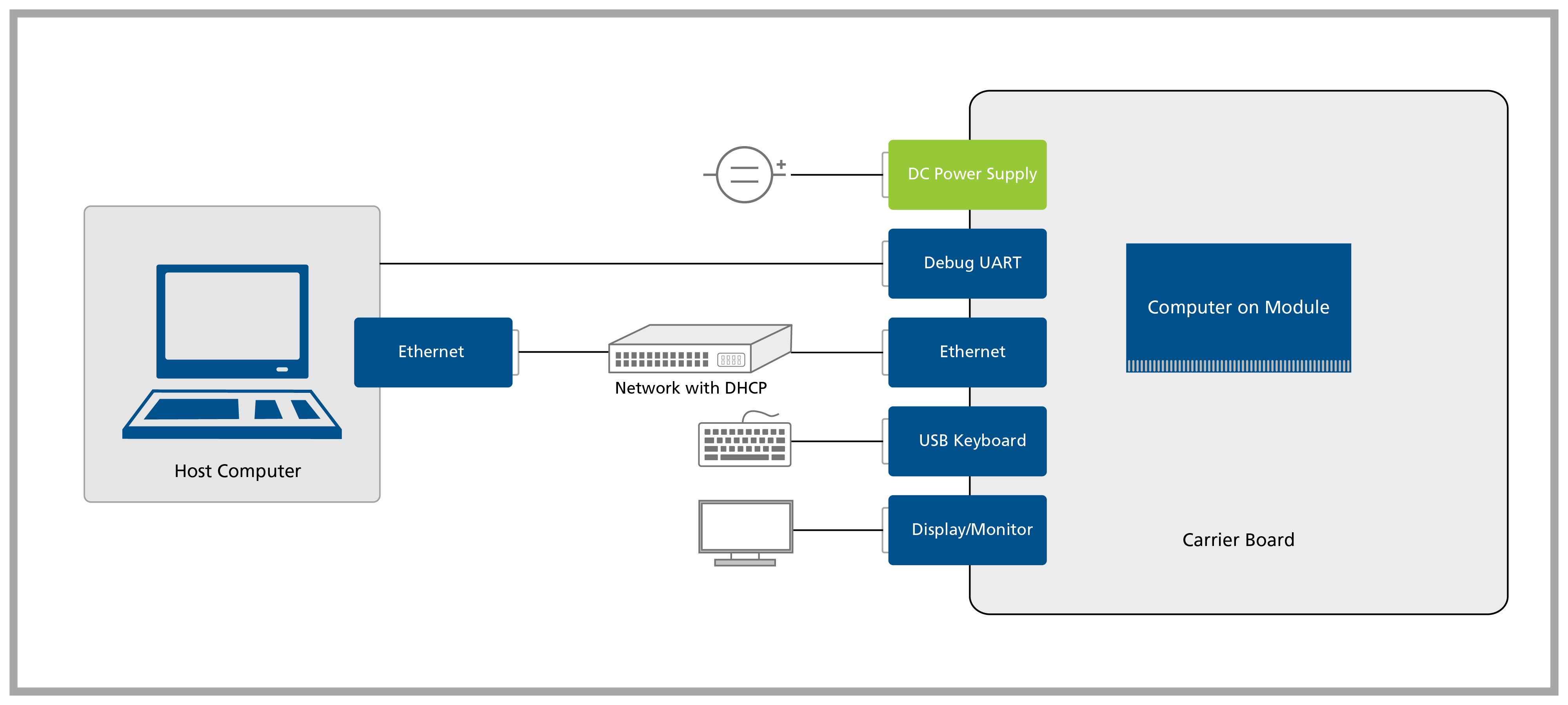
1. Setup Cables
Connect all the cables to your Carrier Board, as demonstrated on the Quickstart Guide for your Carrier Board. Don't forget to connect the display/monitor to the carrier board before power on. HDMI hotplug is not supported.
If don't have a display/monitor available, you can access the user interface remotely over the network using VNC.
2. Download Tezi
Download a Toradex Easy Installer image from Download Toradex Easy Installer.
3. Loading Tezi
3.1 Loading through the USB OTG interface
3.1.1 Put your SoM in Recovery Mode
Don't expect any menu on the Display/Monitor at this moment. The Tezi GUI will only show up after the software be loaded on the next step.
Enter Recovery Mode
Toradex System on Modules are easy to put in recovery mode, so you can flash a new image. We provide simple step-by-step guides to put your module in recovery mode.
Select your module and carrier board below:
Direct links to enter Recovery Mode
Verdin Recovery Mode
Verdin AM62 Recovery Mode
Verdin AM62 and Dahlia Carrier Board Recovery ModeEnter Recovery Mode using a Verdin AM62 with a Dahlia Carrier Board.
Verdin AM62 and Verdin Development Board Recovery ModeEnter Recovery Mode using a Verdin AM62 with a Verdin Development Board.
Verdin AM62 and Yavia Recovery ModeEnter Recovery Mode using a Verdin AM62 with a Yavia.
Verdin iMX8M Mini Recovery Mode
Verdin iMX8M Mini and Dahlia Carrier Board Recovery ModeEnter Recovery Mode using a Verdin iMX8M Mini with a Dahlia Carrier Board.
Verdin iMX8M Mini and Verdin Development Board Recovery ModeEnter Recovery Mode using a Verdin iMX8M Mini with a Verdin Development Board.
Verdin iMX8M Mini and Yavia Recovery ModeEnter Recovery Mode using a Verdin iMX8M Mini with a Yavia.
Verdin iMX8M Plus Recovery Mode
Verdin iMX8M Plus and Dahlia Carrier Board Recovery ModeEnter Recovery Mode using a Verdin iMX8M Plus with a Dahlia Carrier Board.
Verdin iMX8M Plus and Verdin Development Board Recovery ModeEnter Recovery Mode using a Verdin iMX8M Plus with a Verdin Development Board.
Verdin iMX8M Plus and Yavia Recovery ModeEnter Recovery Mode using a Verdin iMX8M Plus with a Yavia.
Apalis Recovery Mode
Apalis iMX6 Recovery Mode
Apalis iMX6 Dual/Quad and Apalis Evaluation Board Recovery ModeEnter Recovery Mode using an Apalis iMX6 Dual/Quad with an Apalis Evaluation Board.
Apalis iMX6 Dual/Quad and Ixora Carrier Board Recovery ModeEnter Recovery Mode using an Apalis iMX6 Dual/Quad with an Ixora Carrier Board.
Apalis iMX8 QuadMax Recovery Mode
Apalis iMX8 QuadMax and Apalis Evaluation Board Recovery ModeEnter Recovery Mode using an Apalis iMX8 QuadMax with an Apalis Evaluation Board.
Apalis iMX8 QuadMax and Ixora Carrier Board Recovery ModeEnter Recovery Mode using an Apalis iMX8 QuadMax with an Ixora Carrier Board.
Colibri Recovery Mode
Colibri iMX6 Recovery Mode
Colibri iMX6 DualLite and Aster Carrier Board Recovery ModeEnter Recovery Mode using a Colibri iMX6 DualLite with an Aster Carrier Board.
Colibri iMX6 DualLite and Colibri Evaluation Board Recovery ModeEnter Recovery Mode using a Colibri iMX6 DualLite with a Colibri Evaluation Board.
Colibri iMX6 DualLite and Iris Carrier Board Recovery ModeEnter Recovery Mode using a Colibri iMX6 DualLite with an Iris Carrier Board.
Colibri iMX6ULL Recovery Mode
Colibri iMX6ULL and Aster Carrier Board Recovery ModeEnter Recovery Mode using a Colibri iMX6ULL with an Aster Carrier Board.
Colibri iMX6ULL and Colibri Evaluation Board Recovery ModeEnter Recovery Mode using a Colibri iMX6ULL with a Colibri Evaluation Board.
Colibri iMX6ULL and Iris Carrier Board Recovery ModeEnter Recovery Mode using a Colibri iMX6ULL with an Iris Carrier Board.
Colibri iMX7 Recovery Mode
Colibri iMX7 and Aster Carrier Board Recovery ModeEnter Recovery Mode using a Colibri iMX7 with an Aster Carrier Board.
Colibri iMX7 and Colibri Evaluation Board Recovery ModeEnter Recovery Mode using a Colibri iMX7 with a Colibri Evaluation Board.
Colibri iMX7 and Iris Carrier Board Recovery ModeEnter Recovery Mode using a Colibri iMX7 with an Iris Carrier Board.
Colibri iMX8X Recovery Mode
Colibri iMX8X and Aster Carrier Board Recovery ModeEnter Recovery Mode using a Colibri iMX8X with an Aster Carrier Board.
Colibri iMX8X and Colibri Evaluation Board Recovery ModeEnter Recovery Mode using a Colibri iMX8X with a Colibri Evaluation Board.
Colibri iMX8X and Iris Carrier Board Recovery ModeEnter Recovery Mode using a Colibri iMX8X with an Iris Carrier Board.
No module and carrier board were selected. Please choose one option from each list above.
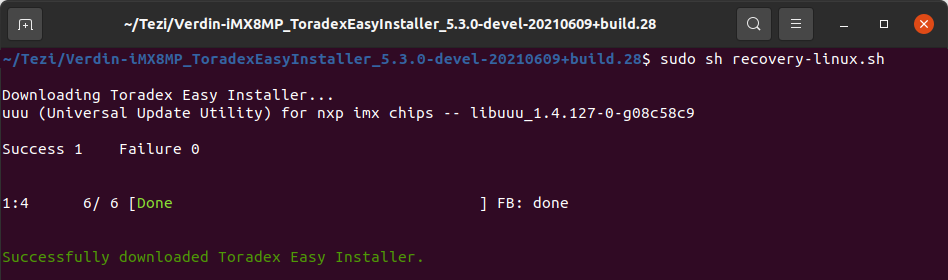
3.1.2 Run the Recovery Mode Script
Unzip the Toradex Easy Installer package you downloaded at the beginning of the article, change to this directory, and use one of the following scripts on the host machine to load and execute the tool through USB OTG interface:
$ cd <unzipped directory>
$ ./recovery-linux.sh
$ cd <unzipped directory>
$ recovery-windows.bat
Apalis TK1 does not have a script for Windows. If you want to load Toradex Easy Installed on an Apalis TK1 module, use a Linux PC.
This process might cause multiple device detections on Windows. Avoid using virtualization since the individual re-enumerated USB devices get not routed through to the virtual machine guest automatically.
During the recovery process, the module connected via USB may re-enumerate several times.
If downloading gets stuck or fails with an error, try starting over from the recovery mode article.
3.2 Loading from External Media (SD Card/USB Stick)
This section describes an alternative method, not officially supported by Toradex, as we technically cannot guarantee that this works all the time and also across different versions. This method relies on Distro Boot, which is configured to boot in the following order on our BSP:
- SD Card
- internal eMMC
- USB Stick
Why would you use an unsupported method, though? Because you are in a situation that does not meet the requirements above or, in other words:
- You have a carrier board that does not allow you to enter recovery mode, or the product enclosing makes it inviable on the field.
- Your product does not allow one to easily use a desktop PC to load Toradex Easy Installer into the SoM on the field.
3.2.1 Prepare the External Media
Unzip Easy Installer into the root directory of the external media (USB stick or SD Card). You will see the following contents, or similar:
$ tree
.
├── boot-tezi.scr
├── image.json
├── imx-boot
├── imx-boot-v10b
├── overlays.txt
├── recovery
│   ├── uuu
│   ├── uuu.auto
│   ├── uuu.auto-v10b
│   └── uuu.exe
├── recovery-linux.sh
├── recovery-windows.bat
├── tezi.itb
├── tezi.png
├── u-boot.bin
└── wrapup.sh
Rename the file boot-tezi.scr to boot.scr. This is the name used by the U-Boot bootloader in our BSP.
3.2.2 Boot Easy Installer
Booting Easy Installer with an image based on our BSP Layers and Reference Images for Yocto Project should work, but keep in mind to match the versions of Tezi and the BSP image. If you mismatch the versions things may still work, but the likelihood is lower.
You might need to adapt the boot.scr to make things work. For this, refer to Distro Boot or ask for help from our developers in the Toradex Community.
And as soon as you have boot.scr in place you can boot Tezi:
From the SD Card:
- Insert the external media on the carrier board.
- power on the carrier board.
From the USB Stick:
- Set up the access to the U-Boot console through the serial port debug UART.
- Insert the USB stick on the carrier board.
- Power on the carrier board.
- Stop U-Boot from booting by pressing any key on your keyboard.
- Run the command
run bootcmd_usb0. It will skip trying to boot from the SD Card and internal eMMC flash, and try to boot directly from the USB.
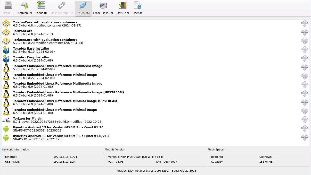
4. Using Toradex Easy Installer
After loading the Toradex Easy Installer into the module's RAM memory, the Tezi GUI will show up in your Display/Monitor.
This process does not write the Toradex Easy Installer to flash. You will have to redo these steps if you power off your module.
You are ready to install images using the tool. See Flash a New Image Using Toradex Easy Installer for instructions on how to proceed.