Unboxing and Setup Cables - SMARC Development Board
Overview
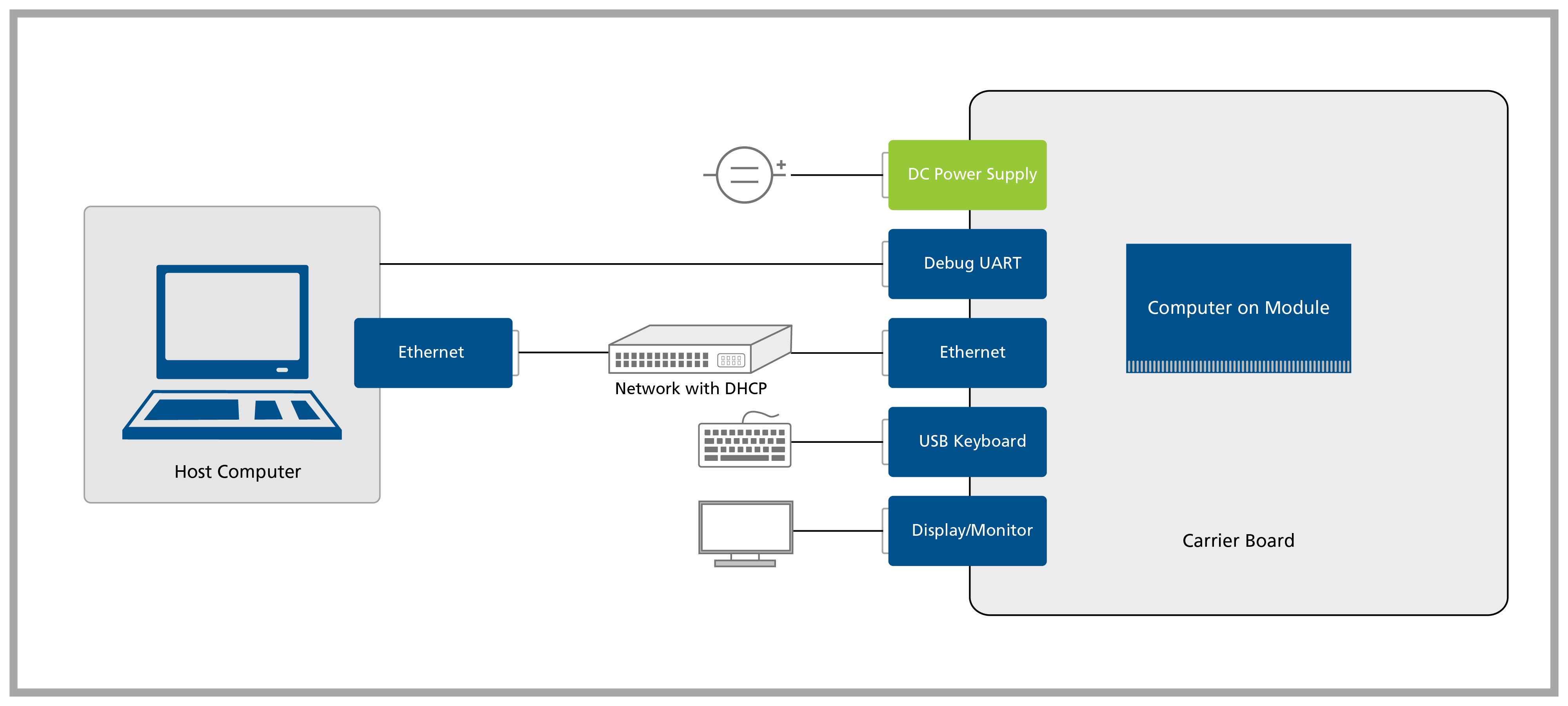
In this first lesson, you will go through the process of unboxing your computer on module and carrier board and assembling the hardware.
A block diagram of the system setup and its connections is presented below for reference.
Prerequisites
Step 1
1.1 Remove the SMARC Development Board and the SMARC System on Module from the blisters.
Note that not all modules come with Wi-Fi/Bluetooth connectivity. Check the datasheet of your module for more information.
For more information on how to connect antennas, refer to the article Operating Toradex Wi-Fi/BT Capable Modules Using Dual and Single Antenna Configuration.
Step 2
Please note down the module serial number before attaching the Heatsink — it’s the easiest way to connect via SSH later!
Screw the SMARC Heatsink Passive on top of the SoM, using the screws that come with it.
Step 3
4.1 Plug an HDMI display in J64 connector.
4.2 Plug a USB keyboard/mouse into the Development Board's J7 connector.
4.3 Plug the Ethernet cable into the Development Board's J41 connector. Alternatively, you can also use the J43 connector.
Ethernet network must provide DHCP and Internet to the module.
4.4 Plug a USB Type-C to Type-A cable into the Development Board's J6 connector.
4.5 Plug the power supply into the Development Board's barrel jack J65.

Make sure that the current capability of the power supply is enough, or the system may shut down unexpectedly. For evaluation purposes, a 12V 2A power supply is recommended.