Unboxing and Setup Cables - Aster
Overview
In this first lesson, you will go through the process of unboxing your computer on module and carrier board and assemble all the hardware.

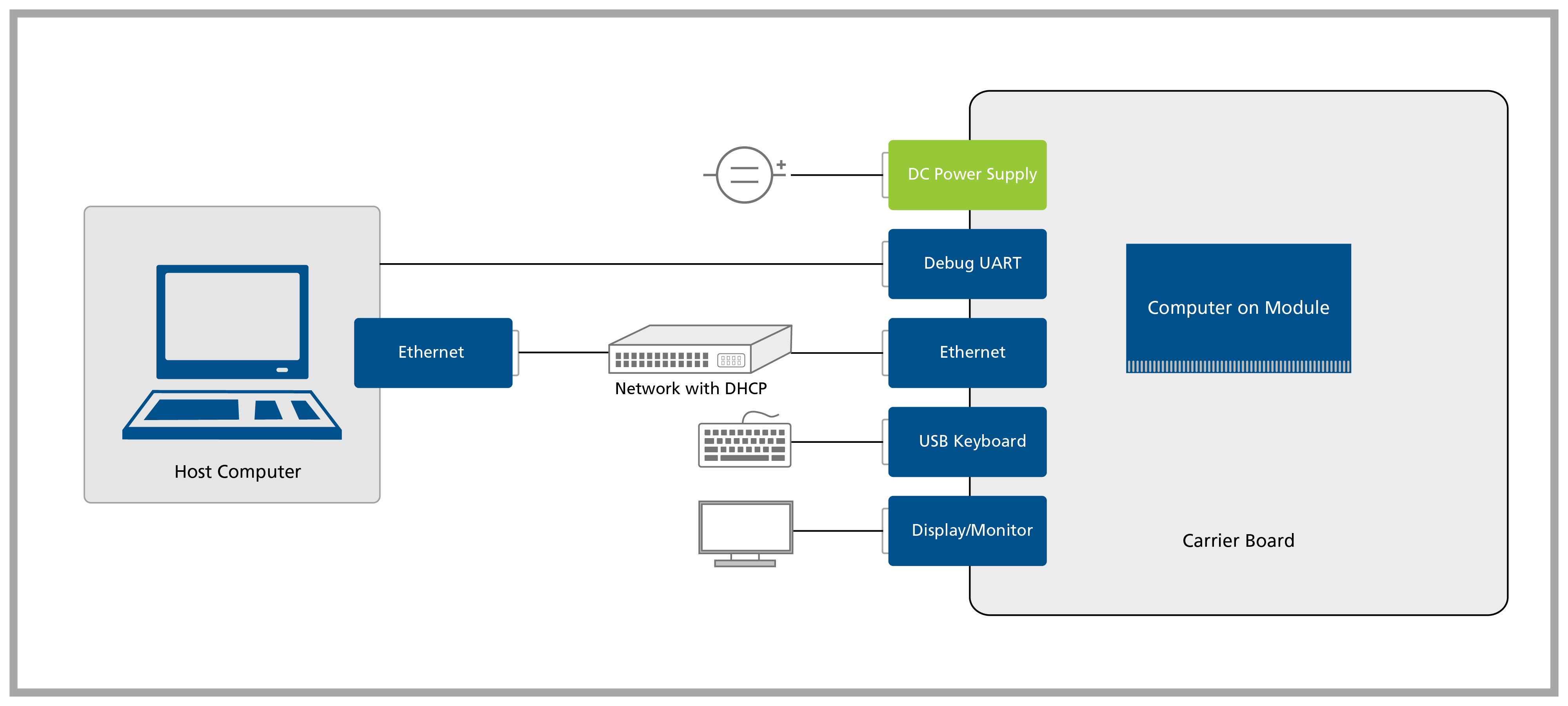
A block diagram of the system setup and its connections is presented below for reference.
Prerequisites
| List of items required |
|---|
| VGA display/monitor |
| USB Micro-A to Type-A (USB Micro-AB receptacle to Type-A) cable |
| Ethernet cable |
| USB keyboard and mouse |
Step 1
Remove the Aster Carrier Board and the Colibri Computer on Module from the blisters.
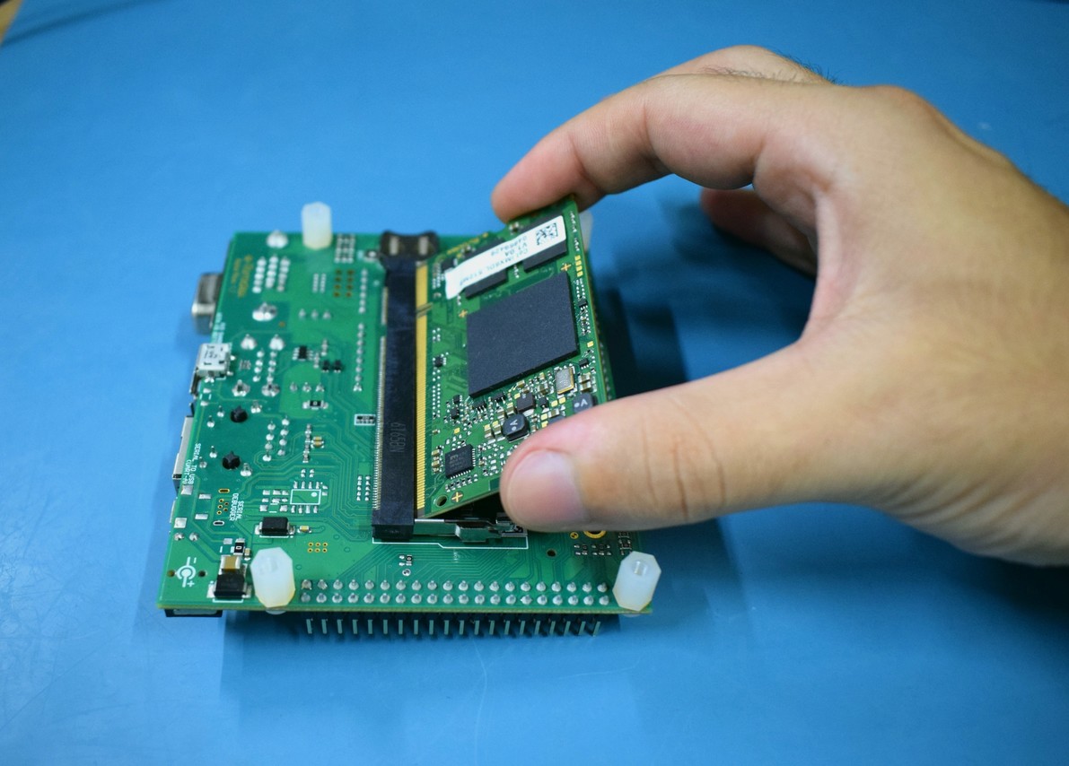
Insert the computer on module into the X1 connector of the Aster Carrier Board on the bottom side, as tight as possible, with the module inclined ~30 to 45 degree in relation to the carrier board.
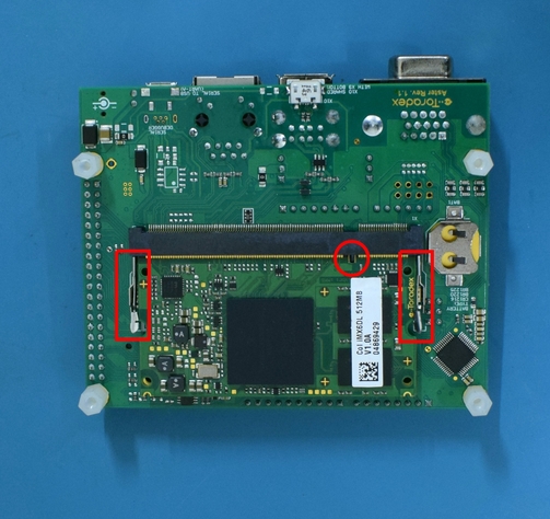
Make sure that the module is well connected to the board. The image below has some checkpoints highlighted.
Step 2
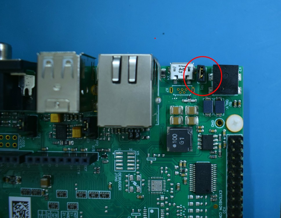
The Aster carrier board provides two ways to power the board: a standard 3.5mm power jack barrel connector using an external DC power supply and a USB micro-B connector (X4). In this guide, we will power the board via the micro USB connector. Therefore, it is necessary to close the jumper JP1, as shown in the image.
The total power consumption of the system depends on the module/peripheral/accessories used. Please note that power available via the micro USB connector may not be sufficient for modules or applications with high power requirements, since this configuration is not fully USB compliant. In such cases, it is recommended to use an external power supply to power the system. While using an external power supply, please remove the shunt jumper (if any) from the USB Power Jumper (JP1) in order to avoid short-circuiting the USB and external power supplies.
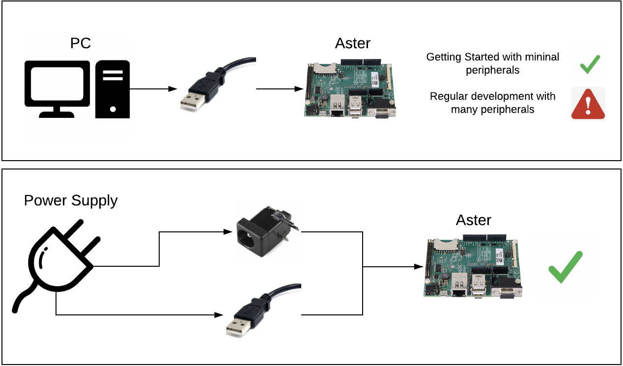
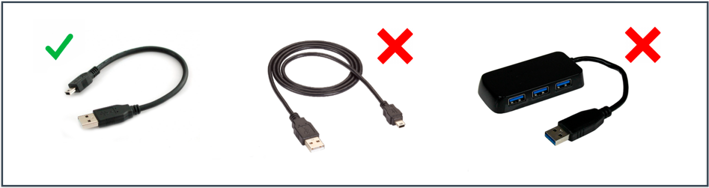
If you decide to power on the board from USB, make sure that you use a high quality and short cable. Long cables are known for making the Aster reboot intermittently due to voltage drop on the cable. Besides that, do not use USB Hubs. Connect the carrier board directly to your PC.
Step 3
Connect a VGA monitor to the Aster's X13 connector.
Connect a USB keyboard to the Aster's X9 connector.
Connect the Ethernet cable to the Aster's X8 connector.
infoEthernet network must provide DHCP and Internet to the module.
:::
- Connect a USB micro-B to type-A cable to X4.
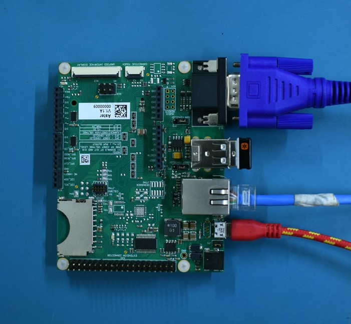
Note that the micro USB connector (X4) can be employed as a means to power the system and also has an integrated USB-serial converter that provides access to the computer on module debug serial port.
Notice that the micro USB connector (X4) can be employed as a means to power the system and also has an integrated USB-serial converter that provides access to the computer on module debug serial port.