Unboxing and Setup Cables - Apalis Evaluation Board
Overview
In this first lesson, you will go through the process of unboxing your System on Module and carrier board and assemble all the hardware.
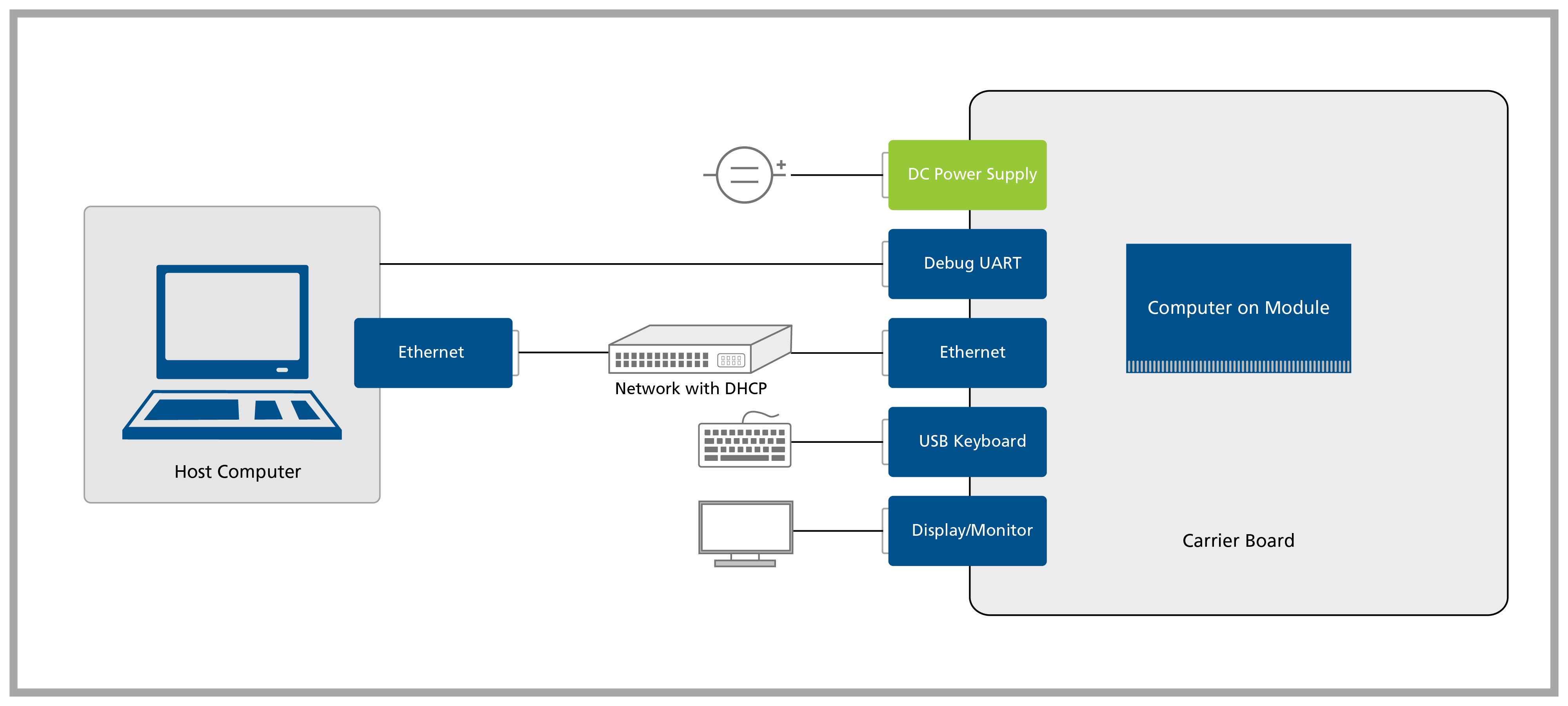
A block diagram of the system setup and its connections is presented below for reference.
Prerequisites
Step 1
1.1 Remove the Evaluation Board and the Apalis Computer on Module from the blisters.
Step 2
Step 3
3.1 Plug a DVI-D monitor into X11.
3.2 Plug an Ethernet cable into X12.
3.3 Plug a USB keyboard into X53 or X54.
3.4 Plug a USB Type-B to Type-A cable into X29. Make sure that the jumpers X39 and X40 are short-circuited in the DVI position, i.e. middle pins.
3.5 Plug a USB Type-B to Type-A cable into X50 if you want to enter Recovery Mode and load the Toradex Easy Installer.
3.6 Plug a 12V power supply into the barrel jack X17 or use a 7-27 V power supply to X15.
Double-check that your power supply is within the rating board limits (7-27V for the X15 connector or 12V for the X17 connector) and that the polarity is not reversed. Also, ensure the power supply's current capacity is sufficient, or the system may shut down unexpectedly. For evaluation purposes, a 12V 2A power supply is recommended.
Make sure that the jumpers JP10 and JP12 are set to USB mode as shown in the image below, once we will use UART-1 via the USB Type-B connector X29.
