Unboxing and Setup Cables - Aquila Development Board
Overview
In this first lesson, you will go through the process of unboxing your System on Module and carrier board and assemble all the hardware.
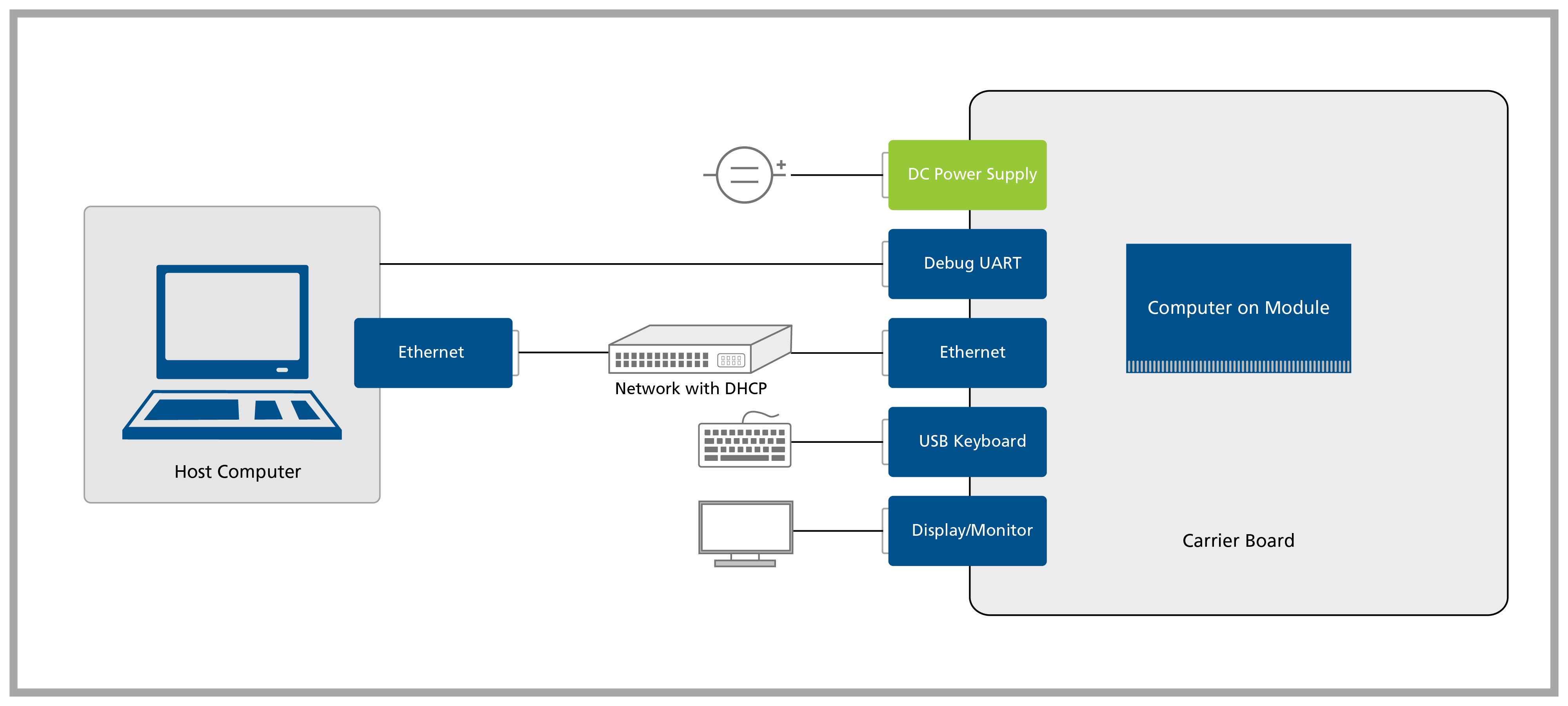
A block diagram of the system setup and its connections is presented below for reference.
Prerequisites
| List of required items |
|---|
| Accessory kit : |
| - 12V 30W power supply |
| - USB Type-C to Type-A cable |
| - Ethernet cable |
| USB keyboard and mouse |
| 2x 2.4GHz SMA antennas |
| 2x SMA to MHF4 cables |
| USB keyboard and mouse |
| List of recommended items |
|---|
| Aquila Industrial Heatsink |
| DisplayPort display/monitor |
Step 1
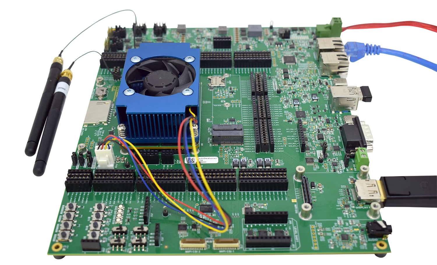
1.1 Unpack the Aquila Development Board and remove the Aquila AM69 from the blisters.
1.2 Unpack the SMA antenna and the SMA to MHF4 cable.
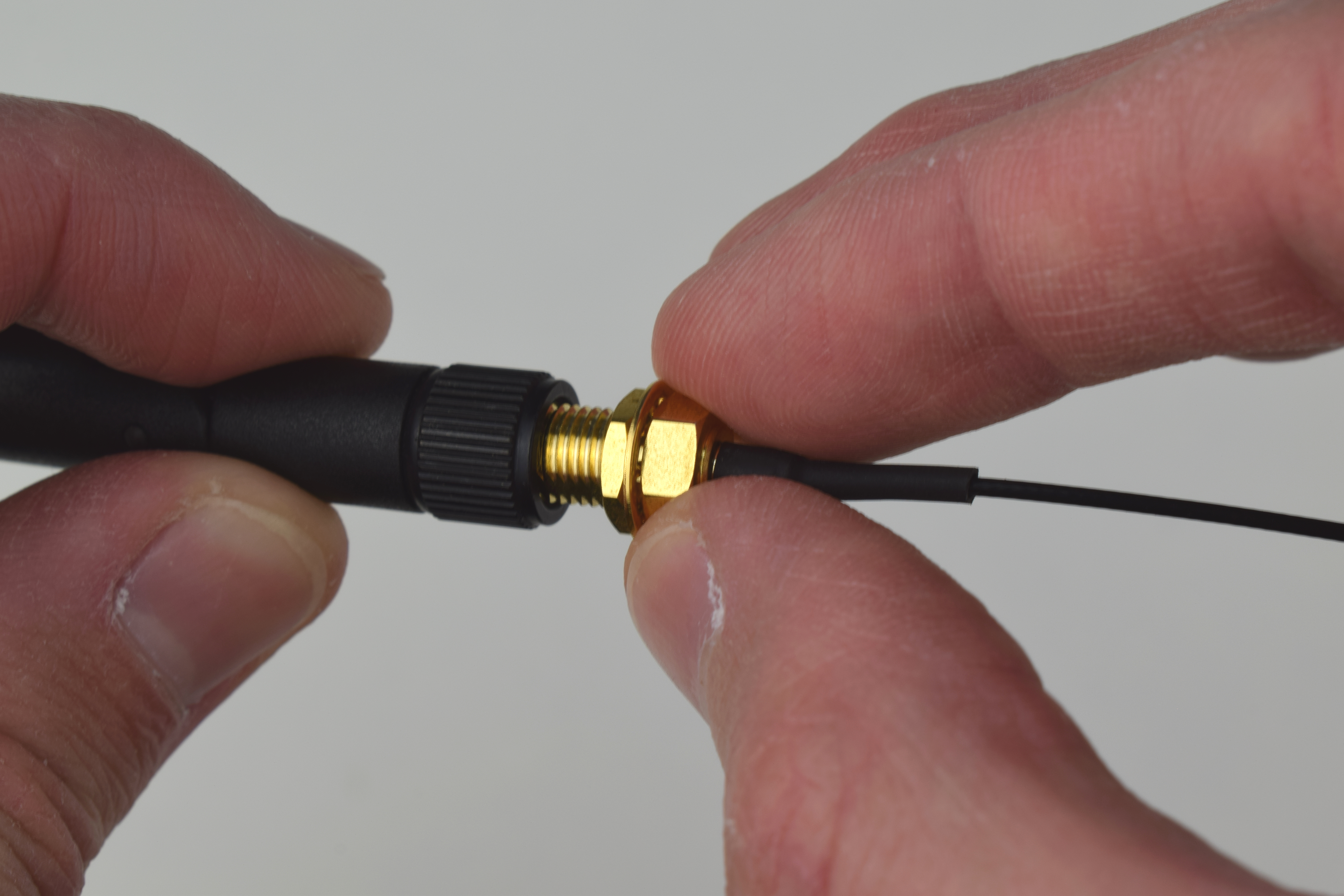
1.3 Connect the SMA antenna to the SMA to MHF4 cable as shown in the picture below:
1.4 Connect the antenna to the MHF4 connector on the module as follows. The MHF4 terminations are tiny and fragile. Because of this, it is strongly recommended not to apply too much pressure when connecting it. Further, be careful not to slip and damage it. Using a tool is also not advised as the risk of damaging the MHF4 connector is higher.
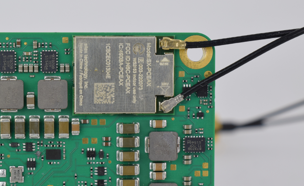
For more information on how to connect antennas, refer to the article Operating Toradex Wi-Fi/BT Capable Modules Using Dual and Single Antenna Configuration.
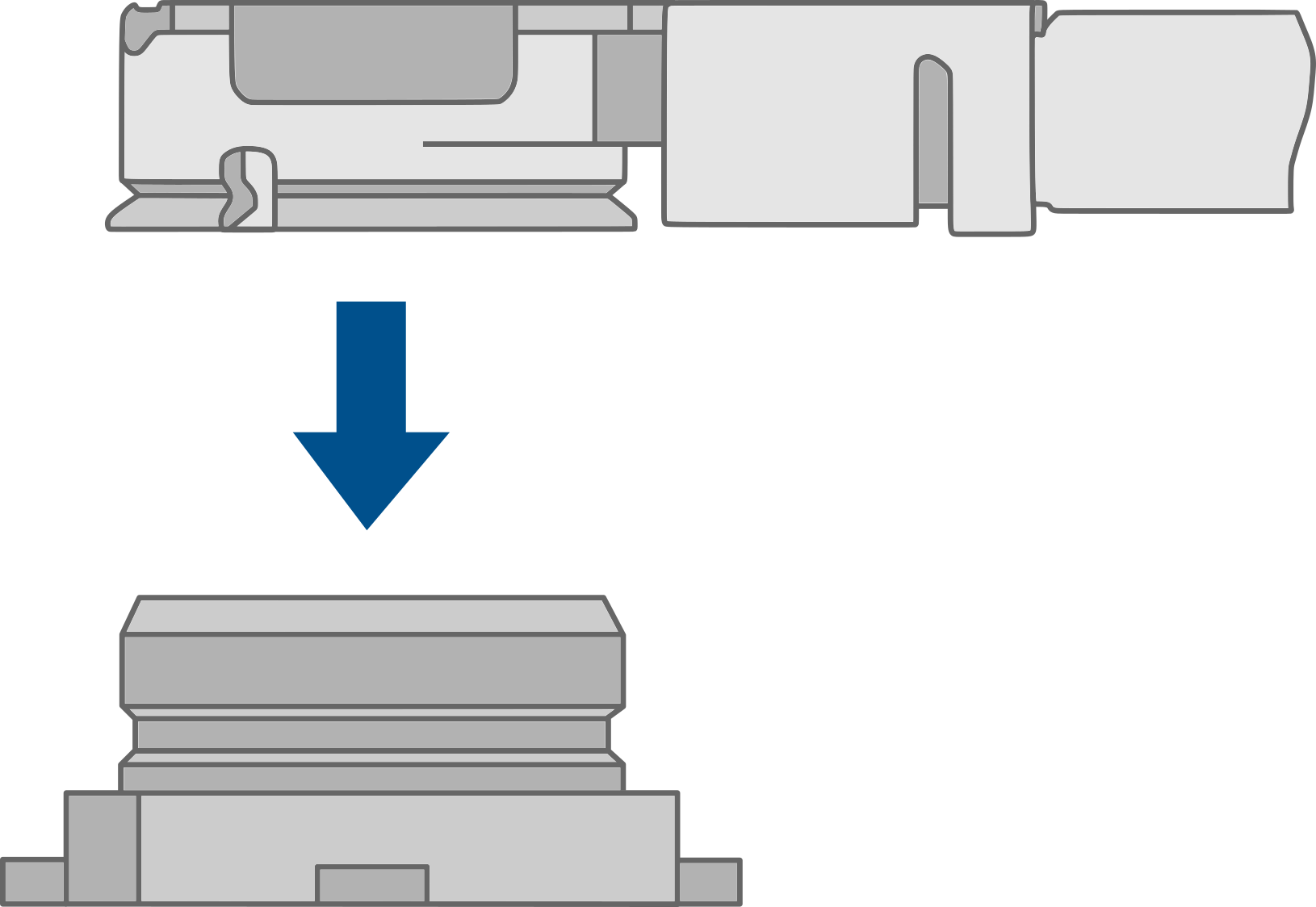
1.5 Align the SoM and carrier board connectors horizontally. Once aligned, carefully press the SoM onto the carrier board until the SoM is seated on all four standoffs, as follows.
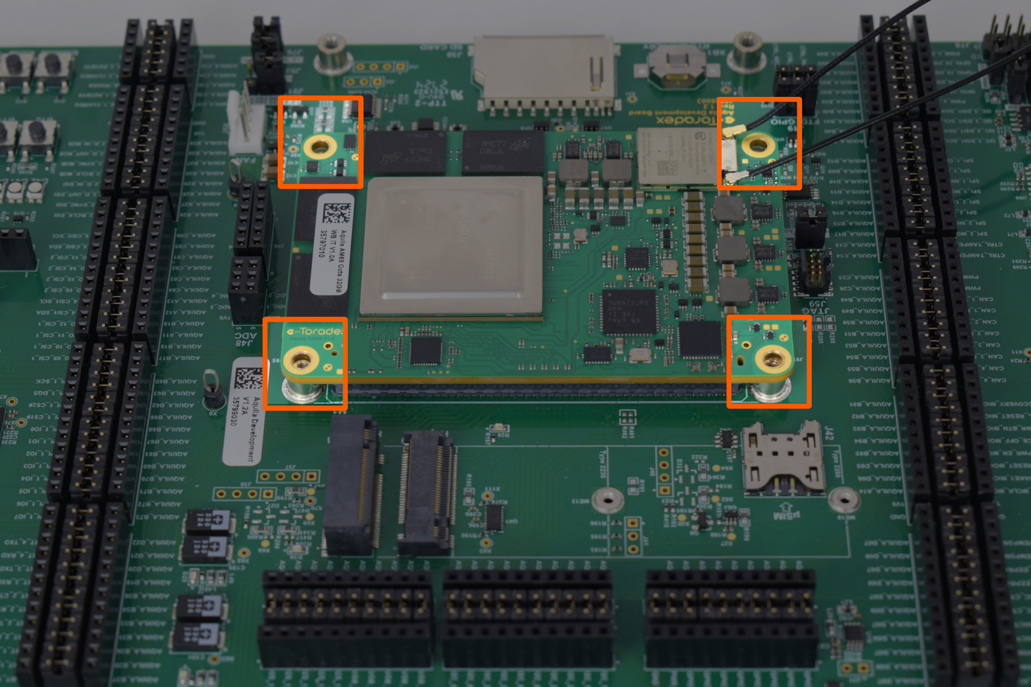
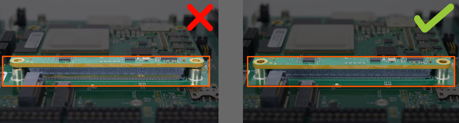
1.6 Check the module's connection to the carrier board and make sure the board-to-board connectors are fully engaged.
Step 2
Please note down the module serial number before attaching the Heatsink — it’s the easiest way to connect via SSH later!
2.1 Screw the heatsink to the carrier board.
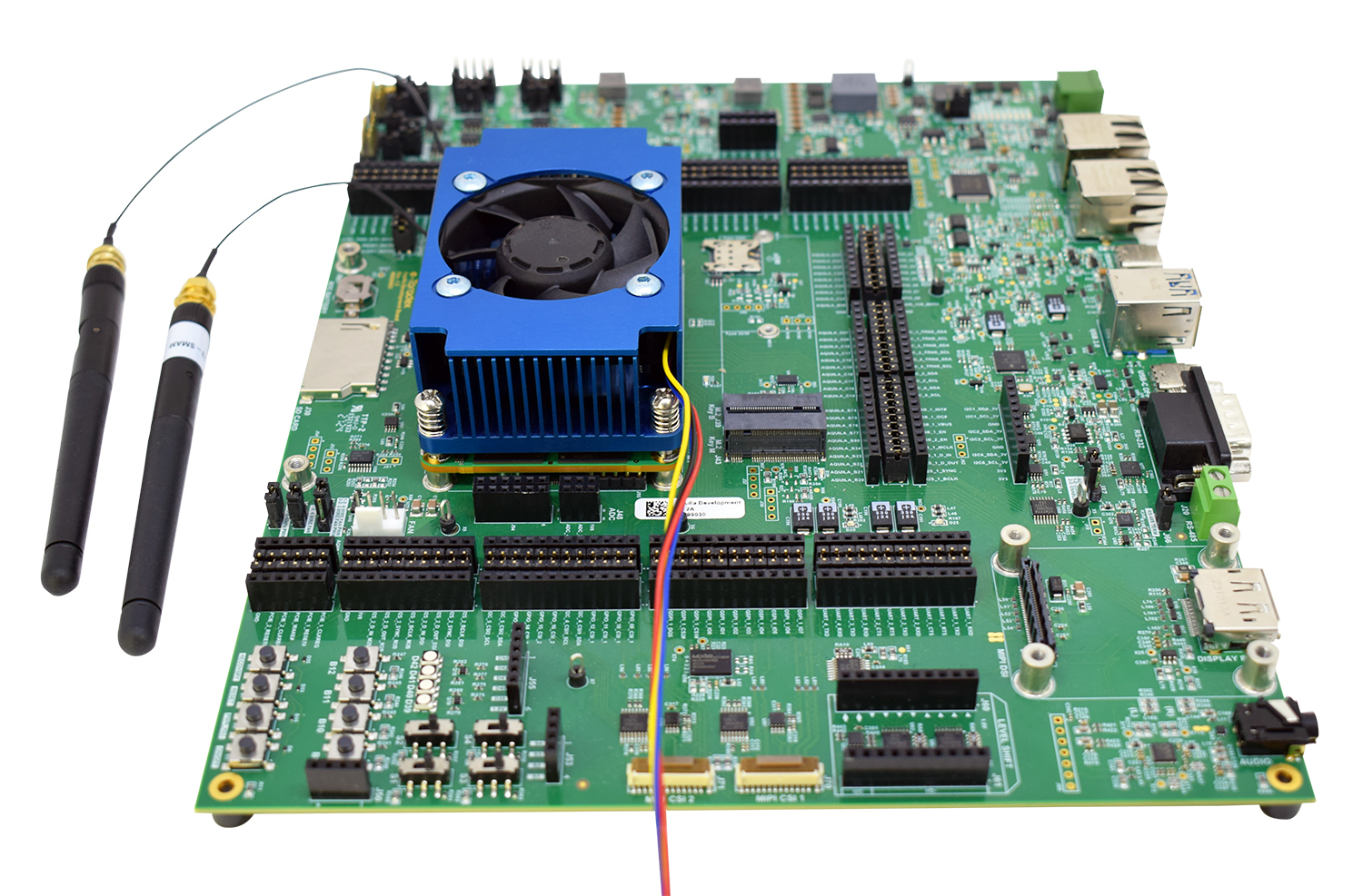
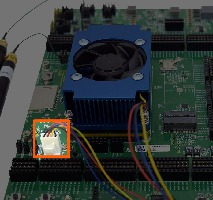
2.2 Now that the heatsink is securely connected, connect the fan's power connector to J56:
Step 3
3.1 Plug a DisplayPort monitor into J27.
3.2 Plug an Ethernet cable into J34.
3.3 Plug a USB keyboard into J33.
3.4 Plug a USB Type-B to Type-C cable into J23 if you want to enter Recovery Mode and load the Toradex Easy Installer.
3.5 Plug a 12V power supply into the J17 connector.
Double-check that your power supply is within the rating board limits 9-24V and that the polarity is not reversed. Also, ensure the power supply's current capacity is sufficient, or the system may shut down unexpectedly. For evaluation purposes, a 12V 2A power supply is recommended.