Unboxing and Setup Cables - Iris
Overview
In this first lesson, you will go through the process of unboxing your computer on module and carrier board and assemble all the hardware.

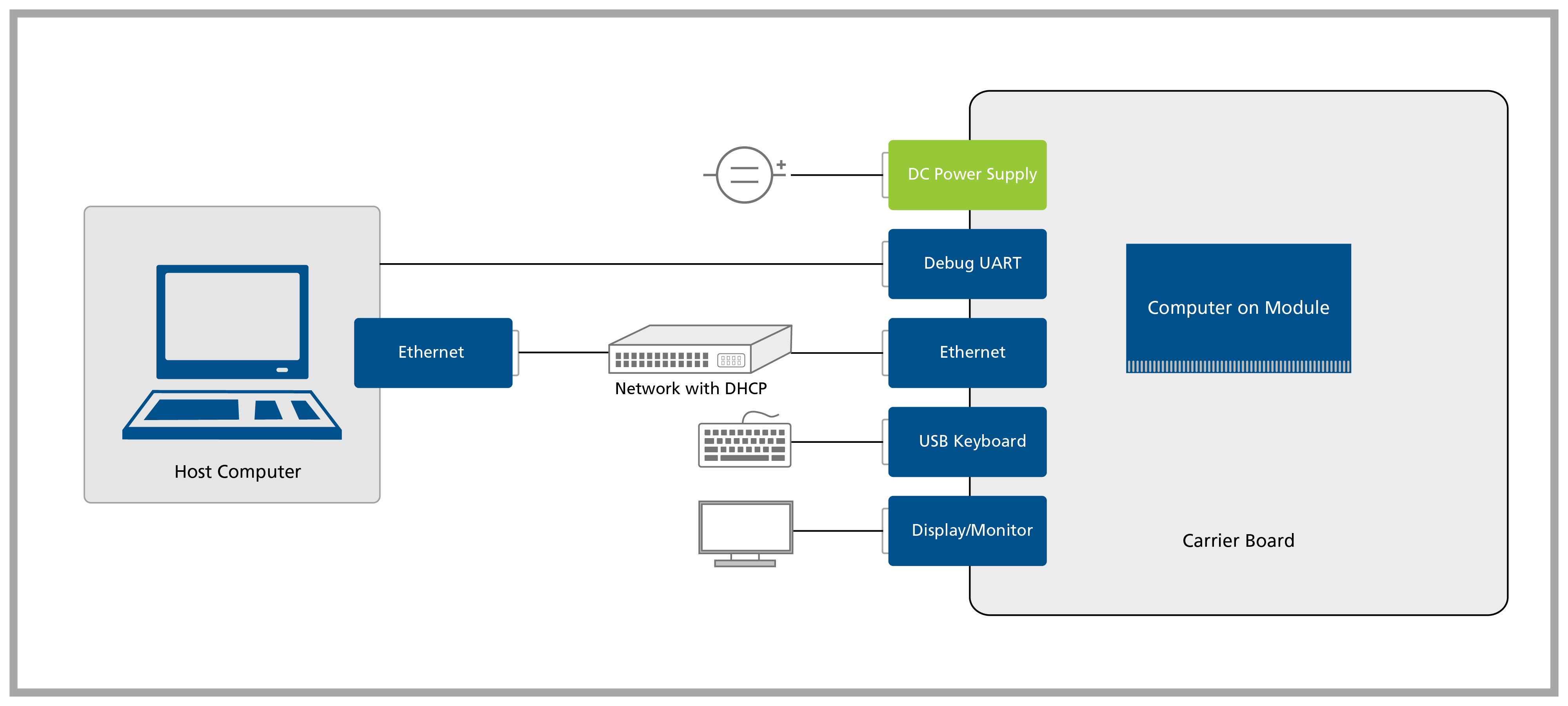
A block diagram of the system setup and its connections is presented below for reference.
Prerequisites
| List of items required |
|---|
| VGA display/monitor and DVI to VGA adapter |
| Accessory kit: |
| - 12V 30W power supply |
| - USB-Serial converter |
| - IDC to DB9 adapter cable (1) |
| - Null modem cable (2) |
| - Ethernet cable |
| USB keyboard and mouse |
(1) As an option to buying the IDC to DB9 adapter, you might assemble one by following the instructions provided on Assembling Serial IDC to DB9 Cable.
(2) The null modem cable comes with the Carrier Board Accessory Kit and it is meant to connect the USB-Serial converter to the IDC to DB9 adapter cable.
A headless setup is possible, though in the Quickstart Guide we will always assume that you have a recommended display attached to the carrier board. If you proceed without a display, skip the lessons that make use of it at your own discretion. As an option, you can follow the Torizon Documentation - just be aware you will not find a walkthrough as thorough as this guide.
The DVI video output is configured to provide an analog signal by default in the Colibri family. Please make sure that your DVI adapter has the analog pins available - see DVI-A or DVI-I for more details.
Step 1
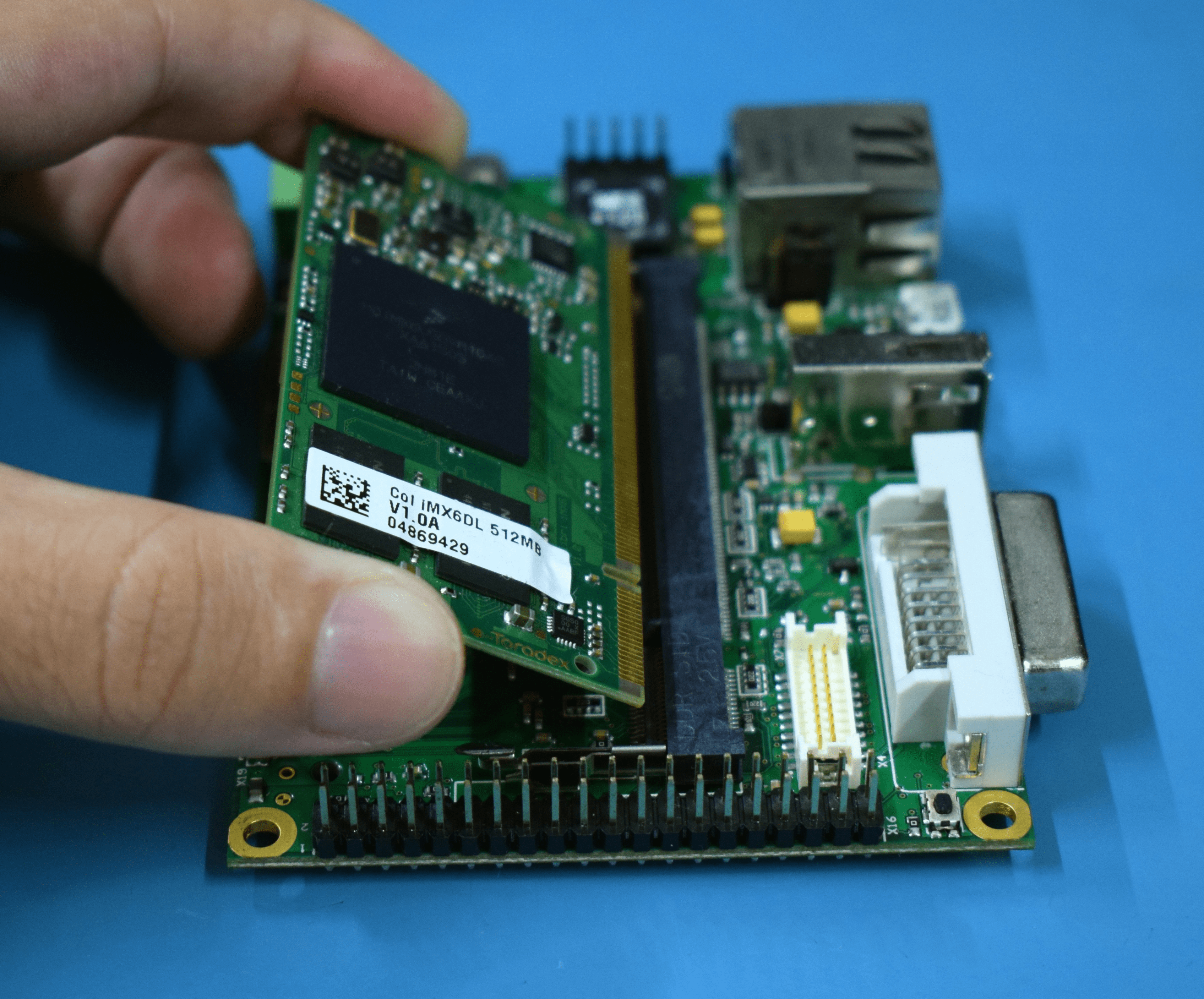
Remove the Iris Carrier Board and the Colibri Computer on Module from the blisters.
Insert the computer on module into the X1 connector of the Carrier Board as tight as possible, with the module inclined ~30 to 45 degree in relation to the carrier board.
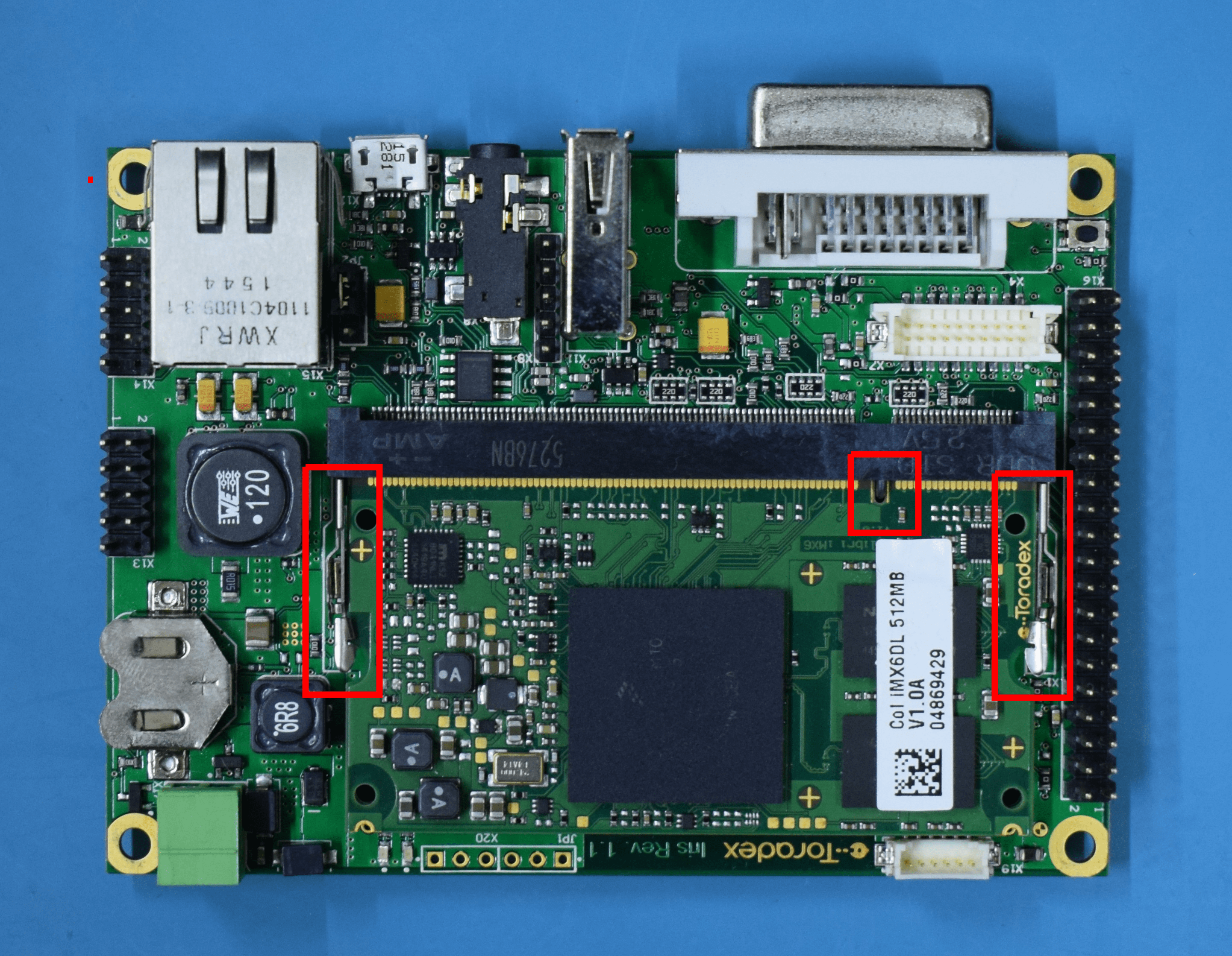
Make sure that the module is well connected to the carrier board. The image below has some checkpoints highlighted.
Step 2
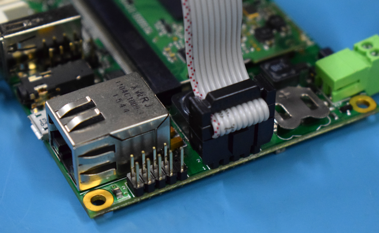
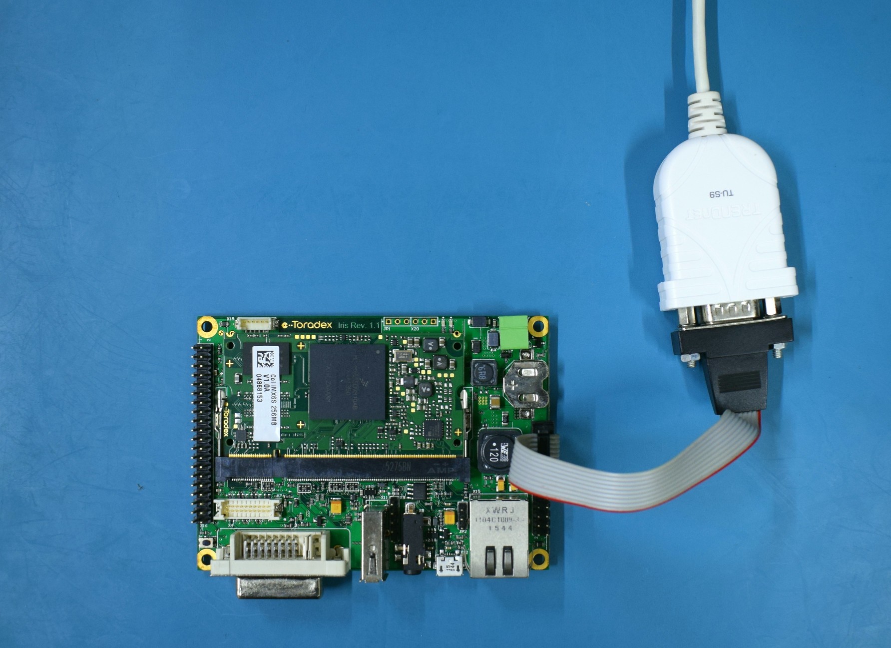
Connect the DB9 to the IDC adapter cable to the X13 connector on the Iris.
The adapter is included in the Toradex Cable Kit, the standard we used is normally called DTK or Intel standard.
Step 3
Connect your host machine to the adapter cable using a serial cable or Serial to USB converter.
Step 4
- Connect the VGA display/monitor to the X4 connector through the DVI to VGA adapter.
The DVI output only has the analog signal enabled by default. To use the digital interface please refer to the FAQ section in the end of this lesson.
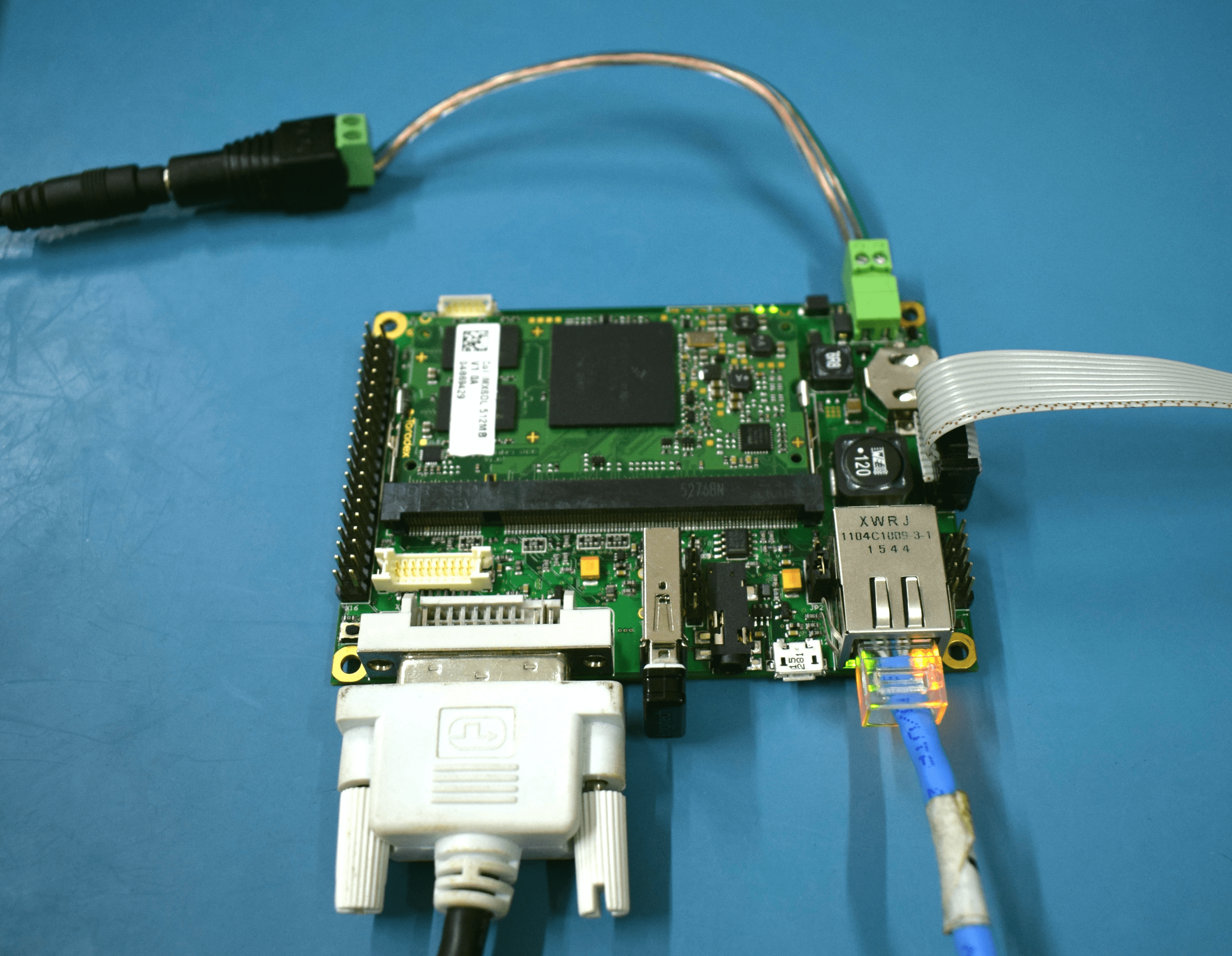
- Connect an Ethernet cable to X15.
Ethernet network must provide DHCP and Internet to the module.
- Connect a USB keyboard to X11.
- Connect a power supply to the barrel jack X8.
Double check that your power supply is within the Iris Carrier Board limits (7-27V) and that the polarity is not inverted. Also, make sure that the current capability of the power supply is enough, or the system may shut down unexpectedly. For evaluation purposes, a 12V 2A power supply is recommended.
FAQ
This FAQ section is meant to provide additional information for the getting-started readers, therefore it may be skipped without prejudice to the progress of the guide.
The DVI video output does not work
The DVI connector provides an analog output (DVI-A and DVI-I compatible) common to all modules from the Colibri family of computer on modules. Although the DVI standard is compatible with VGA, there are some cables and/or devices that do not have the analog interface pins available. If this is the case, the DVI video output will not work by default.