How to Use GPIO on Torizon OS
Introduction
This article presents the essential steps for using GPIO on Torizon OS devices. It does not describe how to customize Torizon OS for using GPIO pins that require any device tree modification. If you want to change pin functionalities, refer to the Pin Multiplexing - Changing Pin Functionalities in the Linux Device Tree article. If your image is already customized to make the GPIO pin available, the instructions from this article are also valid.
After reading this guide, you will be able to incorporate GPIO into your application. This article covers the following topics:
- Check the available GPIO pins in your carrier board
- Test GPIO pins
- Use GPIO inside containers
- Build and run sample applications
This article complies with the Typographic Conventions for Toradex Documentation.
Can I use GPIO user space SysFS?
The Kernel Linux has deprecated GPIO user space SysFS. However, the kernel config CONFIG_GPIO_SYSFS is still enabled on Toradex's BSP to support customers using it in their legacy applications. You can check the configuration by running zcat /proc/config.gz | grep CONFIG_GPIO_SYSFS. For GPIO access from userspace, the new char device API, also known as libgpiod, must be used.
For detailed information on using the command-line tools and the C API, refer to GPIO (Linux).
Torizon OS supports various non-generic features such as GPIO power management keys, GPIO power off, GPIO LED and others explained in GPIO (Linux).
What is libgpiod?
The libgpiod library provides a straightforward API that encapsulates the complexities of the Operating System, including ioctl calls and data structures for working with GPIO. Additionally, the libgpiod project offers a set of command-line tools for GPIO manipulation from the command line. These tools can be used as replacements for scripts previously based on the deprecated sysfs API. They can be helpful for quickly verifying if the targeted GPIO pins are available to your application.
The new user space API uses the /dev/gpiochip devices through Operating System calls to manage GPIOs:
# ls /dev/gpiochip*
/dev/gpiochip0	/dev/gpiochip2	/dev/gpiochip4	/dev/gpiochip6
/dev/gpiochip1	/dev/gpiochip3	/dev/gpiochip5	/dev/gpiochip7
Each entry on the /dev/gpiochip corresponds to a GPIO bank that the operating system has access to.
Prerequisites
- A Toradex Computer on Module with Torizon OS installed
- A configured build environment, as described in the Configure Build Environment for Torizon OS Containers article
Pin Standardization
On Torizon OS, the GPIO pins are named based on the module's edge connector type. Verdin and Colibri modules use the name SODIMM for GPIO pins, while Apalis modules use MXM3. This naming convention simplifies pin identification and usage, allowing users to refer to pins by name instead of bank and line. Follow the next steps to identify and test GPIO pins.
Find Available GPIO Pins
This section provides a step-by-step guide on how to identify available GPIO pins of a SoM and locate the corresponding connector on both the SoM and the carrier board.
1. Identify SODIMM/MXM3 Pins on Modules
Each SoM offers multiple dedicated GPIO pins. Some of those are reserved for other interfaces. Additionally, several modules' pins can be used as GPIO if their primary function is not in use. To ensure compatibility across modules, prioritize the utilization of dedicated GPIO pins.
Refer to the GPIO section of the SoM's datasheet for information on available GPIO pins. If you are performing a quick evaluation, you can select a GPIO pin directly available on a carrier board connector, as explained in the next section.
The following example shows the GPIO table for the Verdin iMX8M Plus.
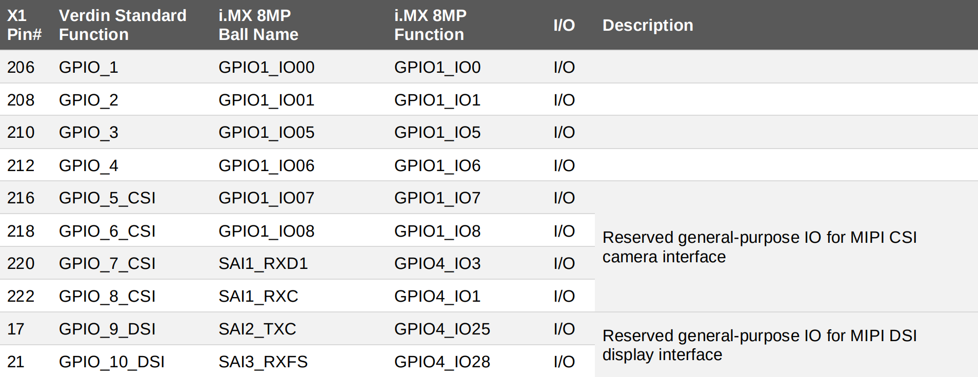
Also, ensure that the chosen pin is not reserved for any other interfaces (which is the case for pin 216 in the above example).
2. Identify GPIO Pins on the Carrier Board
Refer to your carrier boards' datasheet or schematic and identify a SODIMM/MXM3 Pin connected to the GPIO interface and available through a connector on the carrier board.
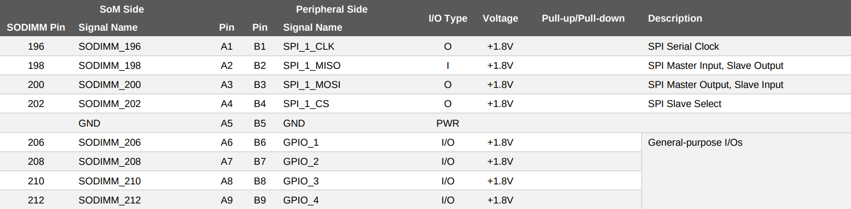
For instance, you can find valuable information in the Verdin Development Board datasheet. In the IO pin configuration table you will find the GPIO pins, SODIMM pins, and signal names available through the X5 connector:
3. Record the Pin Details
Once you have selected a GPIO pin, write down its SODIMM/MXM3 Pin, and the corresponding connector.
The relevant information for the GPIO_3 pin is listed below:
- Connector location: X5
- SODIMM Pin: 210
Use Non-Dedicated GPIO Pins
Using GPIO pins primarily dedicated to other functions, like SPI, requires device tree modification. However, this is not covered in this article. If you need to modify the device tree to use GPIO pins, see How to Write Device Tree Overlays.
Hardware Setup to Test a GPIO Pin
In this section, you will learn how to set up the hardware for testing GPIO pins.
1. Locate the GPIO Pin on Your Carrier Board
The carrier board's datasheet or schematic can help you locate the GPIO pin. Alternatively, you can directly search for the GPIO pin using the labels on your carrier board.
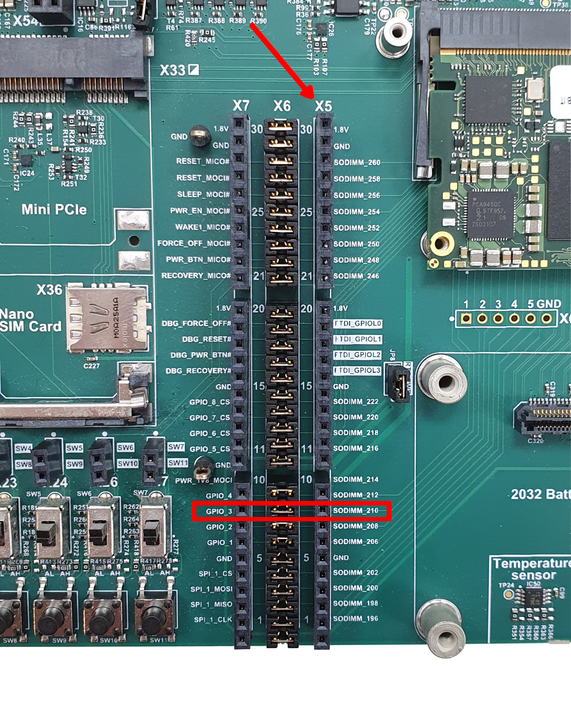
The image below shows the GPIO_3 connector location on the Verdin Development Board.
2. Prepare your Testbed
To test the GPIO pin, you can utilize either a multimeter or an LED to verify the logic level of the connector. When using an LED, ensure you match the voltage and current of both the LED and the GPIO pin. If necessary, consider using a driver circuit to power the LED correctly.
The Verdin Development Board already provides LEDs with driver circuits for quick evaluation:
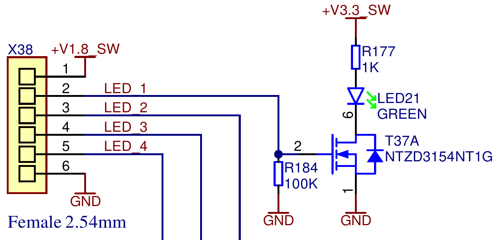
Thus, we can directly connect the GPIO pin to the carrier board's LED interface, as follows:
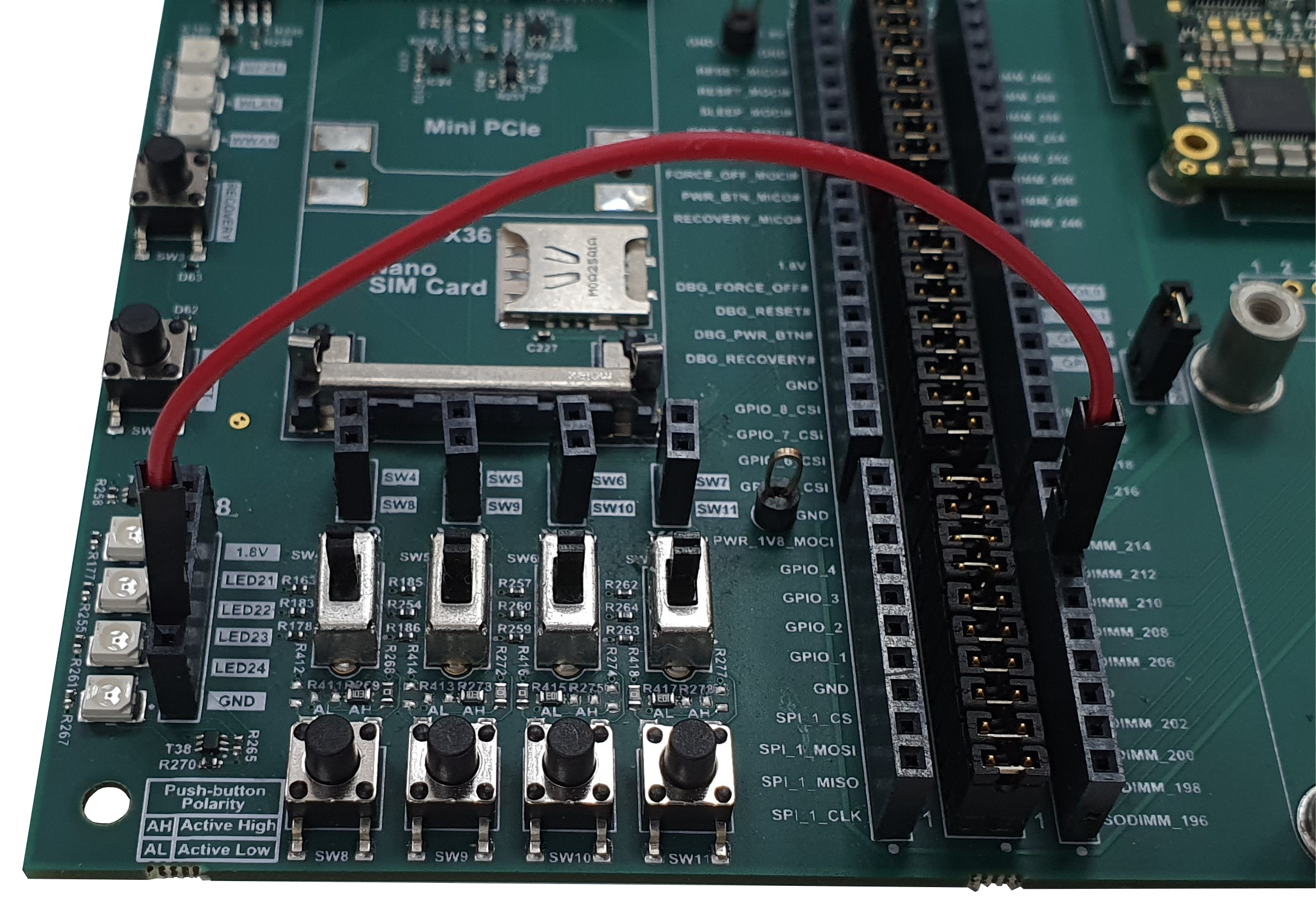
Note that the GPIO_3 pin of the Verdin iMX8M Plus, accessible via the SODIMM_210 pin on the Verdin Development Board, was used. If you have different hardware and are unsure where to begin, refer to the How to Use GPIO on Torizon OS article.
The TTL level for Colibri and Apalis I/O is 3.3V, while for Verdin is 1.8V. Do not apply 3.3V signals to Verdin I/O.
Test GPIO Pins from a Container
In this section, you will learn how to make the GPIO pin accessible from a Docker container. Then, you will check if the pin works as expected before using it in your application.
1. Run the Toradex Pre-built Container
Toradex provides a pre-built container with libgpiod installed, which enables you to confirm that the GPIO pin is working as expected.
To download the image and build the container for testing, run the following command on the board's terminal:
# docker run --rm -it -v /dev:/dev --device-cgroup-rule='c 254:* rmw' torizonextras/arm64v8-gpiod
To download the image and build the container for testing, run the following command on the board's terminal:
# docker run --rm -it -v /dev:/dev --device-cgroup-rule='c 254:* rmw' torizonextras/arm32v7-gpiod
2. Ensure Access to the GPIO Pin from the Container
Take note of its bank and line, as they will be needed for testing using libgpiod commands, such as gpioset.
# gpiofind <SODIMM/MXM3_PIN>
For instance, you would get the following output for SODIMM_210 of the Verdin Development Board:
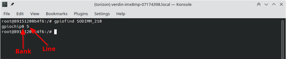
It means that our pin is located at bank 0 and line 5.
If you are experiencing difficulties finding a GPIO pin, you can alternatively execute the command provided below and manually search for the pin.
# gpioinfo
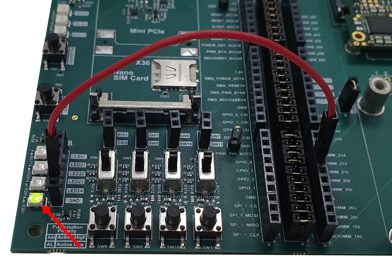
3. Toggle the GPIO Pin
Change the logic level of the pin and verify if it works as expected.
# gpioset <bank> <line>=<logic_level>
For example, we could turn the LED on by running the following command.
# gpioset 0 5=1
Command-line Tools Usage
After launching the container, you can run any libgpiod command inside the container. For detailed information, refer to the section Command Line Tools on GPIO (Linux).
Best Practices for Production
Use SODIMM/MXM3 Pin Names
Although it is acceptable to use bank and line for testing, using the SODIMM/MXM3 Pin names helps you simplify your code. SODIMM/MXM3 Pin names are also guaranteed to not change during Torizon/BSP upgrades, minimizing the impact of OS upgrades on your application.
Specify Accessible Devices within the Container
To test the GPIO pin, we provided container access to all GPIO banks using the --device-cgroup-rule='c 254:* rmw' flag. However, it is recommended to only share the required banks with the container using the --device flag when in production. For example:
# docker run --rm -it --device /dev/gpiochip0 <yourDockerHubUsername>/<DockerHubRepository>
If the container needs to access multiple GPIO banks, you will need to specify the --device argument multiple times, as shown in the following example:
# docker run --rm -it --device /dev/gpiochip0 --device /dev/gpiochip1 --device /dev/gpiochip2 <yourDockerHubUsername>/<DockerHubRepository>
Use GPIO as a Non-root User
A best practice for Dockerfile is to run containers as non-root users. This approach ensures that containers only have the necessary permissions. In this case, you will have to add the user to the GPIO group by adding the following command to your Dockerfile:
RUN usermod -a -G gpio torizon
Dockerfile example
ARG BASE_NAME=debian-imx8
# Image for arm64 architecture
ARG IMAGE_ARCH=linux/arm64/v8
# Image for arm architecture
#ARG IMAGE_ARCH=linux/arm/v7
ARG IMAGE_TAG=4
ARG DOCKER_REGISTRY=torizon
FROM $DOCKER_REGISTRY/$BASE_NAME:$IMAGE_TAG
RUN apt-get -y update && apt-get install -y --no-install-recommends \
gpiod \
&& apt-get clean && apt-get autoremove && rm -rf /var/lib/apt/lists/*
# Allow the user torizon to use GPIOs
RUN usermod -a -G gpio torizon
# Add sample bash scripts for convenience
COPY ./*.sh /usr/local/bin/
# Run the container using the torizon user
USER torizon
CMD [ "bash" ]
Use Case Example
This section provides a step-by-step guide on listing and toggling GPIO lines using the libgpiod library. For that, Toradex provides multiple code samples. To use them, perform the following steps:
-
Download the source code from GitHub: There are samples written in different programming languages:
Those applications are part of the Toradex-provided Samples.
-
Modify the source code to match the GPIO pin you are using: Let's suppose the following setup:
- Sample: Python
- Module: Verdin iMX8M Plus
- Target GPIO pin: SODIMM 206
Look at the second commit. It shows the modifications made to a Torizon IDE Extension template to use GPIO pins.
In that case, you would modify the source code as follows:
main.py- gpiolineName = None
+ gpiolineName = "SODIMM_206"
gpioChip = "/dev/gpiochip0"If you keep the
gpiolineNameasNone, the application displays the available GPIO lines ingpioChip:Application's output snippetgpiochip0 - 32 lines
Line 0: SODIMM_206 unused output
Line 1: SODIMM_208 unused output
Line 2: unnamed unused output
Line 3: unnamed interrupt output
Line 4: unnamed sd-vsel output
Line 5: SODIMM_210 unused output
Line 6: SODIMM_212 unused outputNote that you can refer to the GPIO pin by its name as described in the Pin Standardization section.
infoThis sample uses the gpiod Python module for providing GPIO interfacing capabilities.
- Build and run the container. On Torizon OS, there are two possible approaches:
- Use the Torizon IDE extension for Visual Studio Code, which provides automated tasks and facilitates embedded application development. Since this sample is based on a Torizon IDE Extension template, the extension is the recommended approach for running it.
- Use Dockerfiles, Docker Compose files and Docker CLI commands to Deploy Container Images to Torizon OS.
Troubleshooting
If you are unable to control a GPIO pin from the command line using libgpiod commands as explained in Test GPIO Pins from a Container, you should make sure that:
- You are running your tests inside the a docker container with
libgpiodinstalled. You must share your devices (/dev) directory with the container. The container must have permission to access the/devdirectory. All these conditions should be met if you run the recommended container as specified in Run the Toradex Pre-built Container. - Your chosen pin is a dedicated GPIO pin. To check if your pin is a dedicated GPIO pin, follow the steps at Find Available GPIO Pins.
If you wish to use the GPIO function for a non-dedicated pin, you must:
- Verify that the pin has a GPIO alternate function available
- Write a device tree overlay to enable the pin to be used as GPIO
Both of these steps are explained in detail in Case Oriented Example: Enabling a GPIO Pin.
Next Steps
This article presented the first steps for using GPIO on Torizon OS devices. To support your next steps, Toradex provides comprehensive documentation that will enhance your experience of embedded application development. We recommend exploring the following articles:
- How to enable Peripheral Access for other devices and interfaces.
- Deploy Container Images to Torizon OS.
- What is the Torizon IDE Extension for Visual Studio Code.