First Steps with CSI Camera Set 5MP AR0521 Color (Linux)
Introduction
This article provides information on how to start working with the CSI Camera Set 5MP AR0521 Color.
Adding a Yocto Project layer is required. It is not possible to use TorizonCore Builder to add this driver.
The following topics will be covered:
For details about using Video4Linux and GStreamer tools to interact with cameras and collect video frames, see Cameras on Toradex System on Modules.
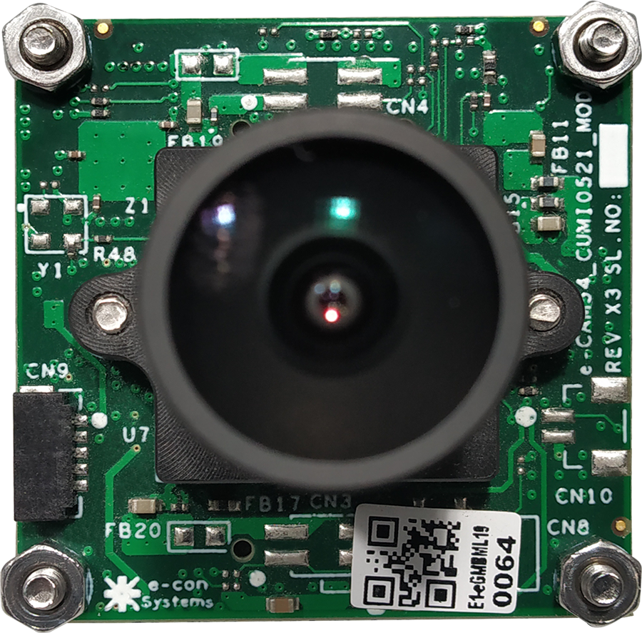
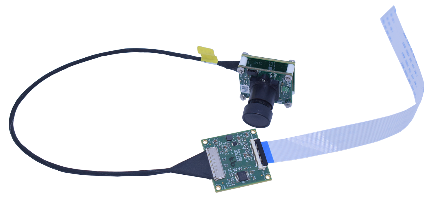
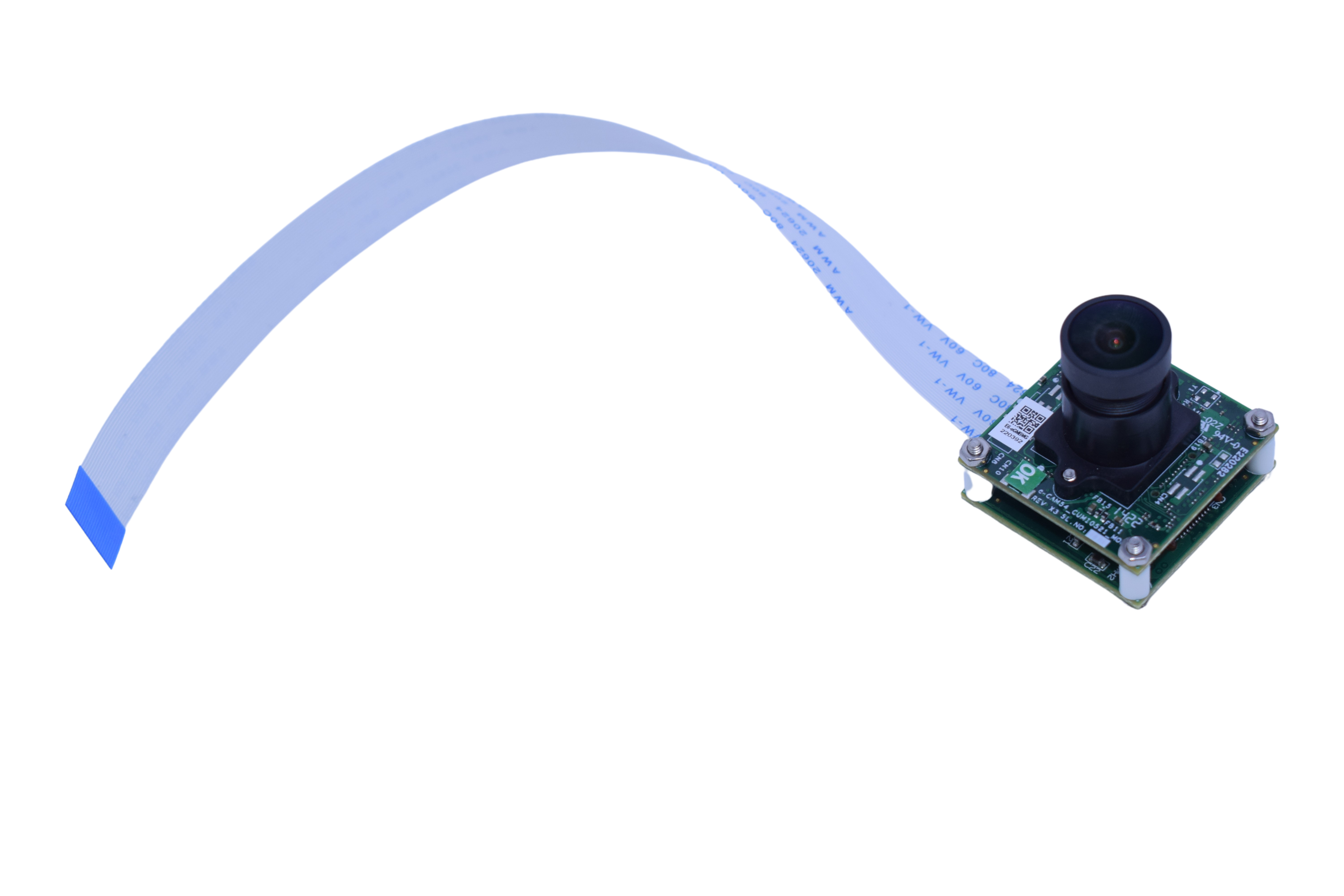
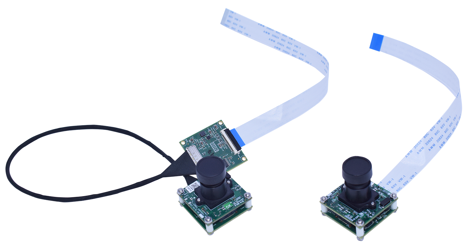
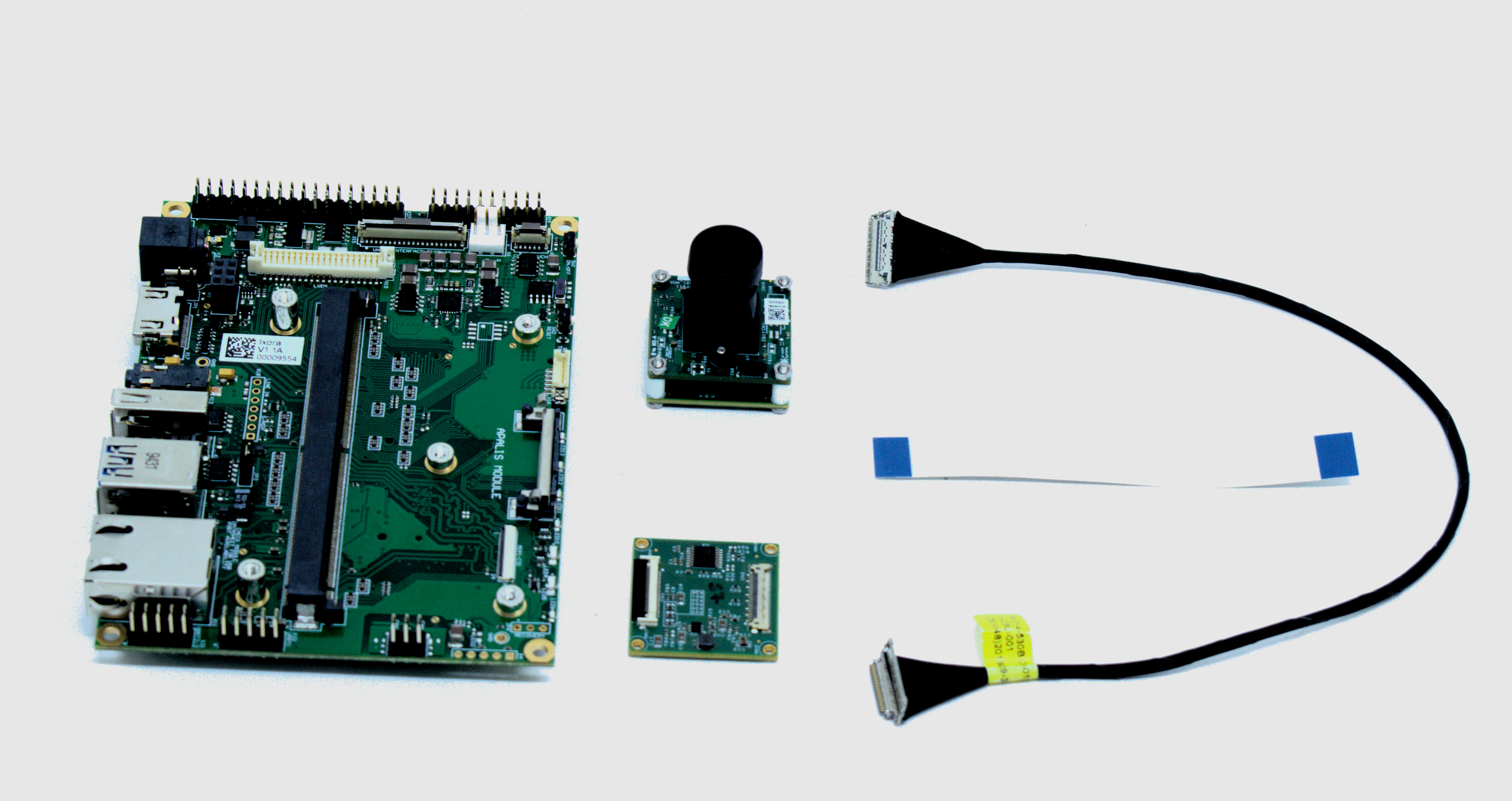
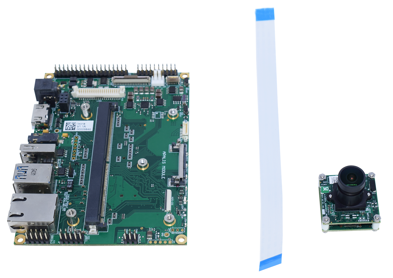
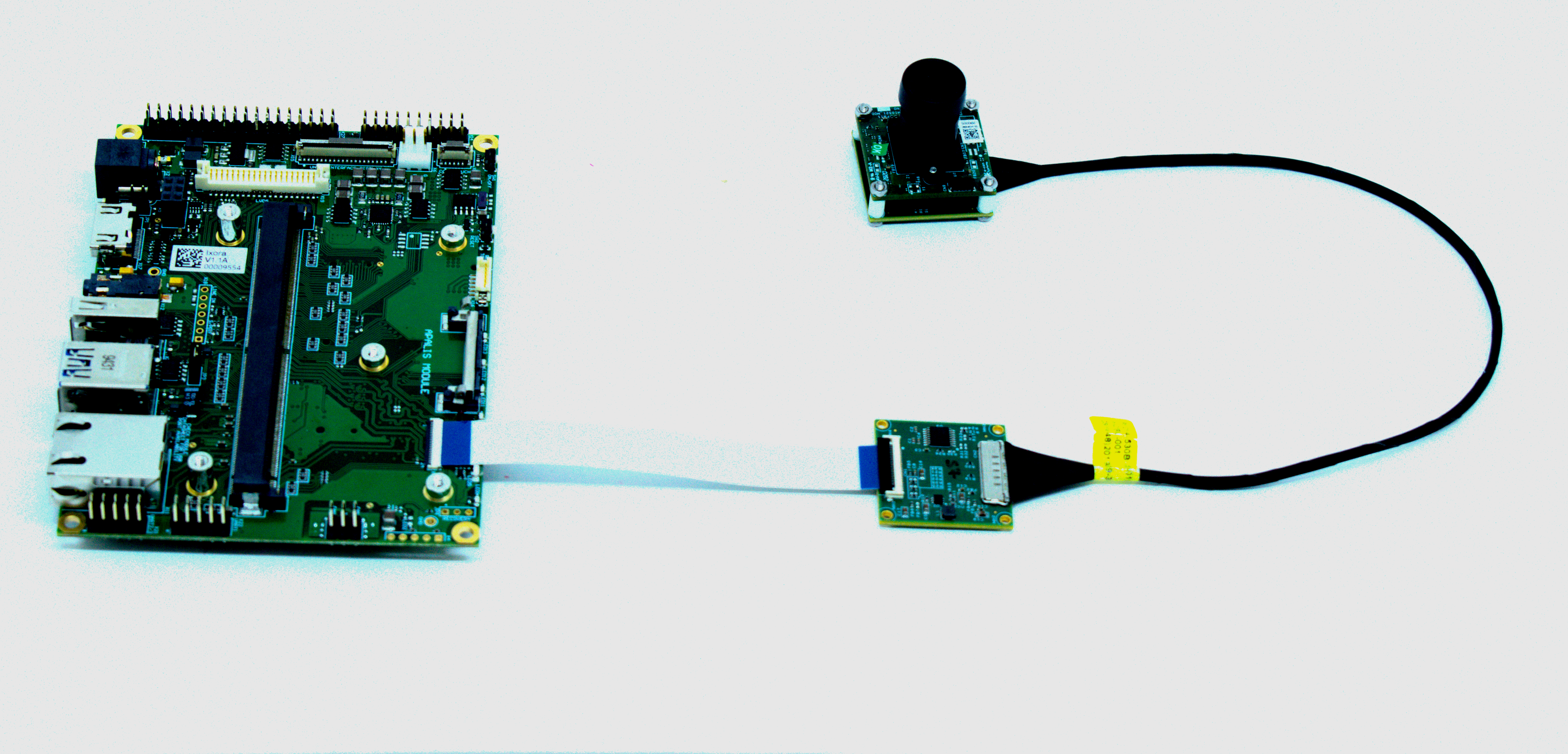
There are 2 versions (V1.0A and V1.1A) of the the CSI Camera Set 5MP AR0521 Color. The key difference is that the older version is a three board solution, while the V1.1A changed to a two board solution.
Please check the Revision History to assert which one you are using.
Hardware Setup
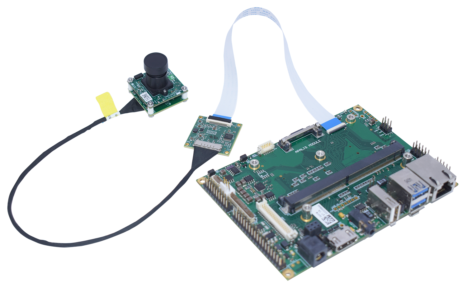
What I need to order
The CSI Camera Set 5MP AR0521 Color can be ordered with many Toradex computers on modules and carrier boards. See the compatible products.
Where do I order
All the products can be ordered online in the Toradex Webshop.
Cable Connection
This topic provides pin connection details regarding connecting the CSI Camera Set 5MP AR0521 Color to the carrier boards.
The flat ribbon cable (used to connect the carrier board and the camera adaptor) is very fragile. If your camera does not work, make sure to test the cable connections on the flat cable.
Please refer to the instructions below for connecting the display to your specific carrier board.
Connection to Ixora
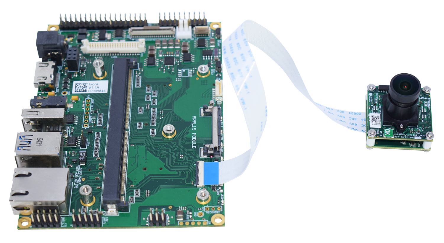
See the picture below for the direct connection from the camera to the Ixora board. Make sure to connect the pin 1 side of the CSI camera to the respective pin 1 of the carrier board (MIPI-CSI Connector X28).
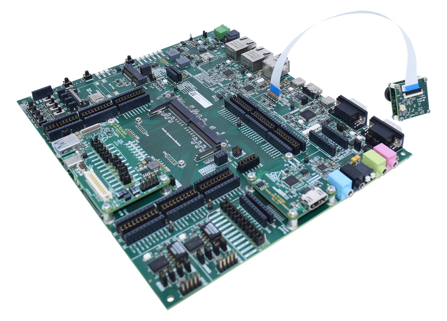
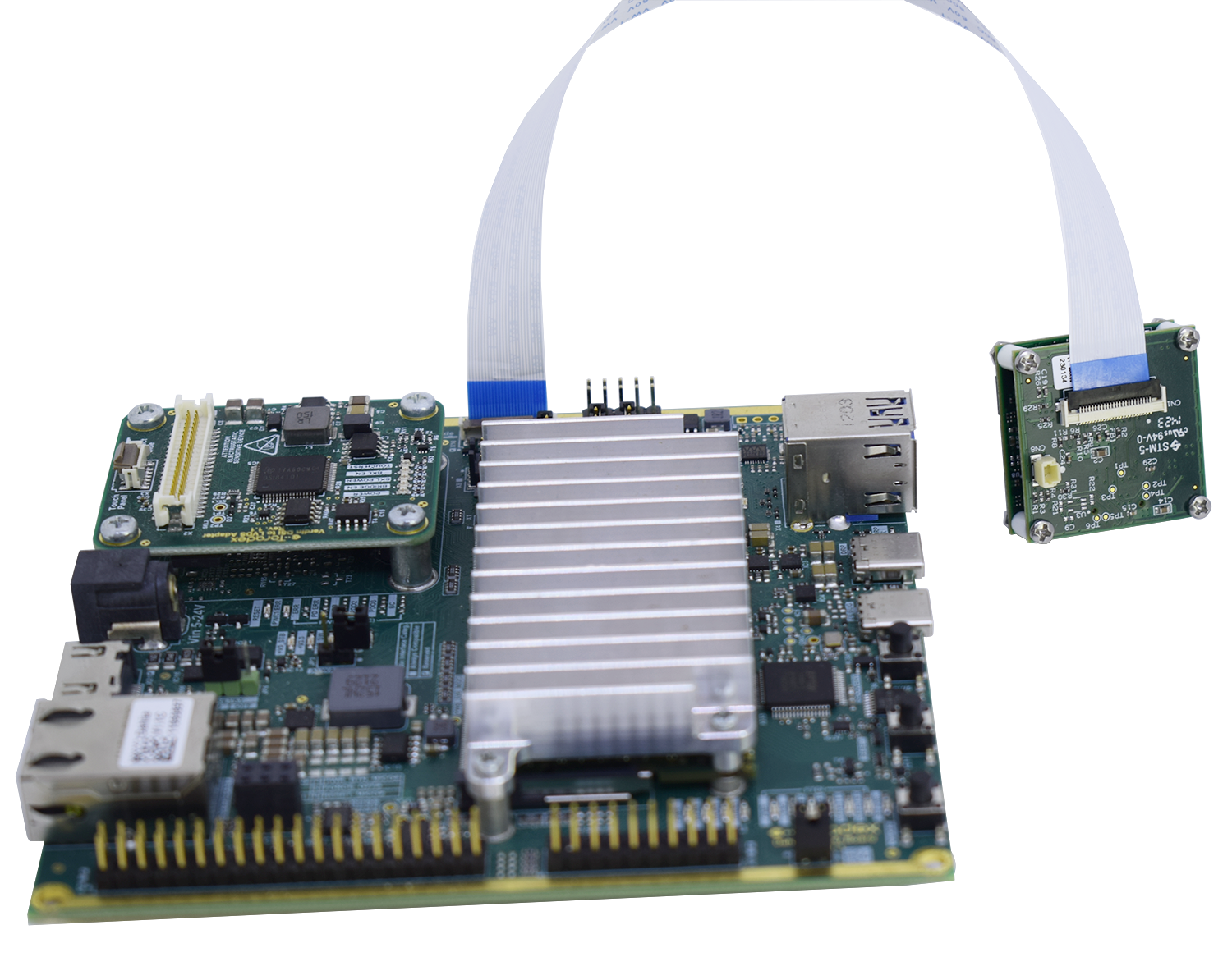
Connection to Verdin Development Board
Connect the camera to the Verdin Development Board as indicated in the figure below. The MIPI-CSI Camera Interface is on connector X47. Make sure to connect the pin 1 side of the CSI camera to the respective pin 1 of the carrier board.
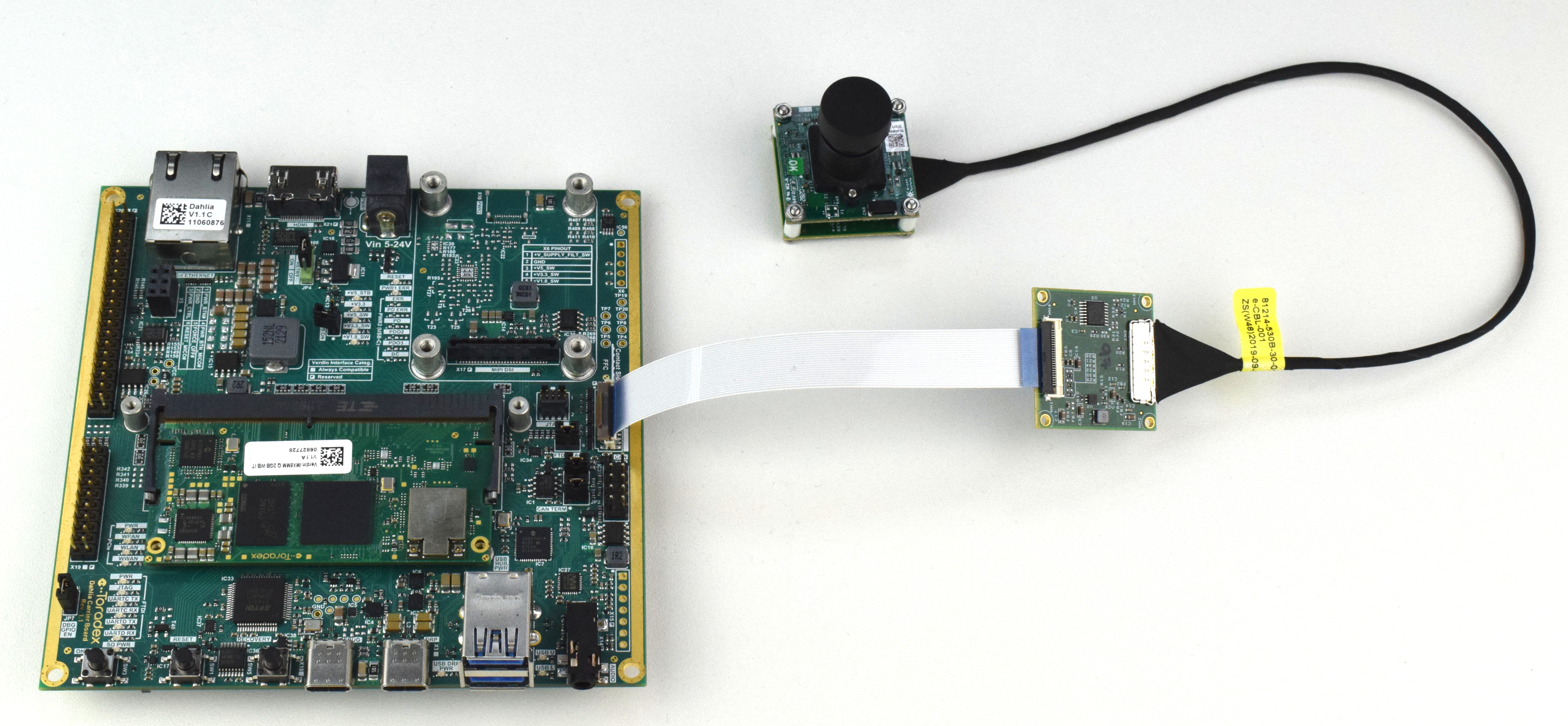
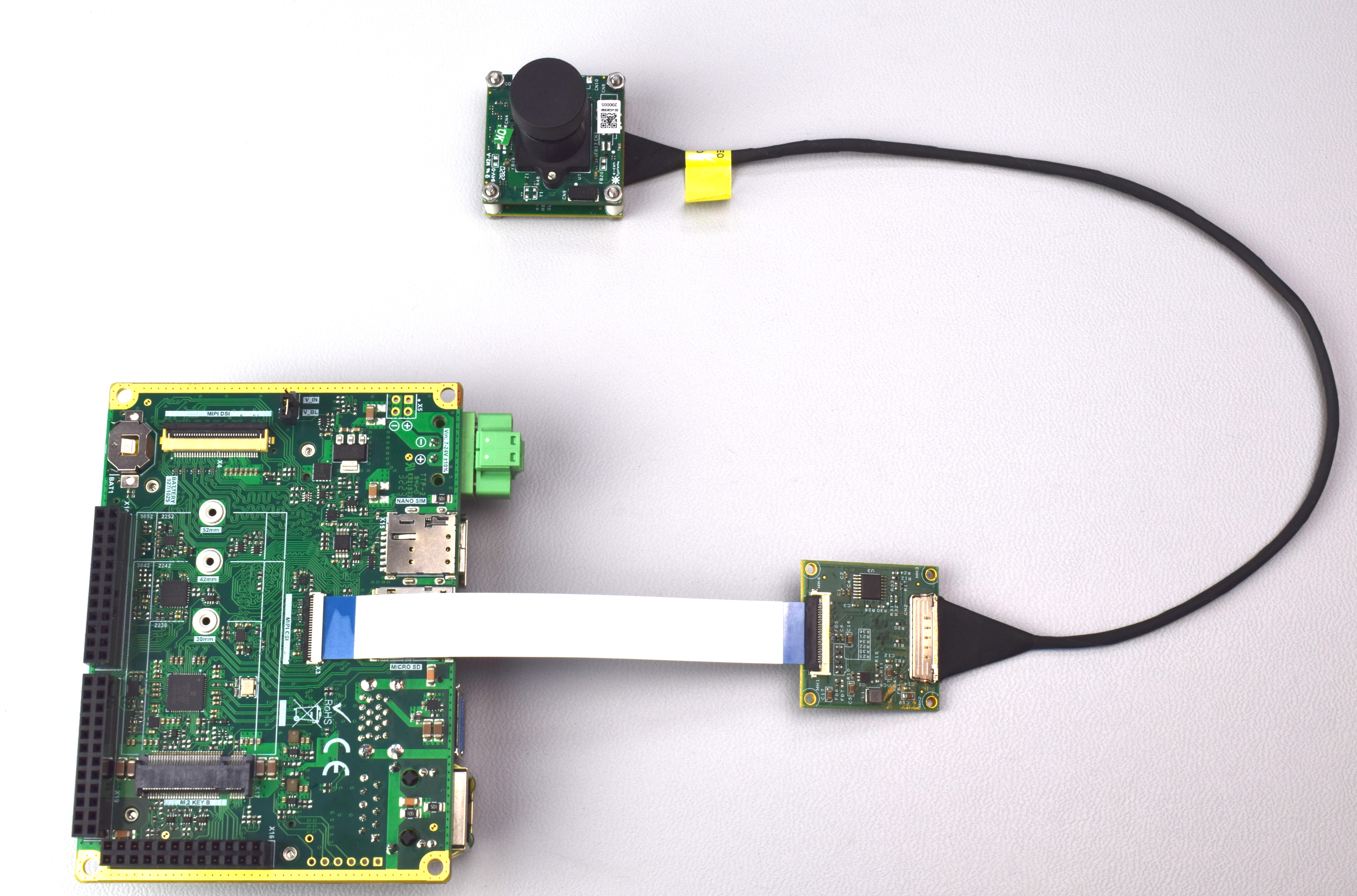
Connection to Dahlia Carrier Board
Connect the camera to the Dahlia Carrier Board, as indicated in the figure below. The MIPI-CSI Camera Interface is on connector X16.
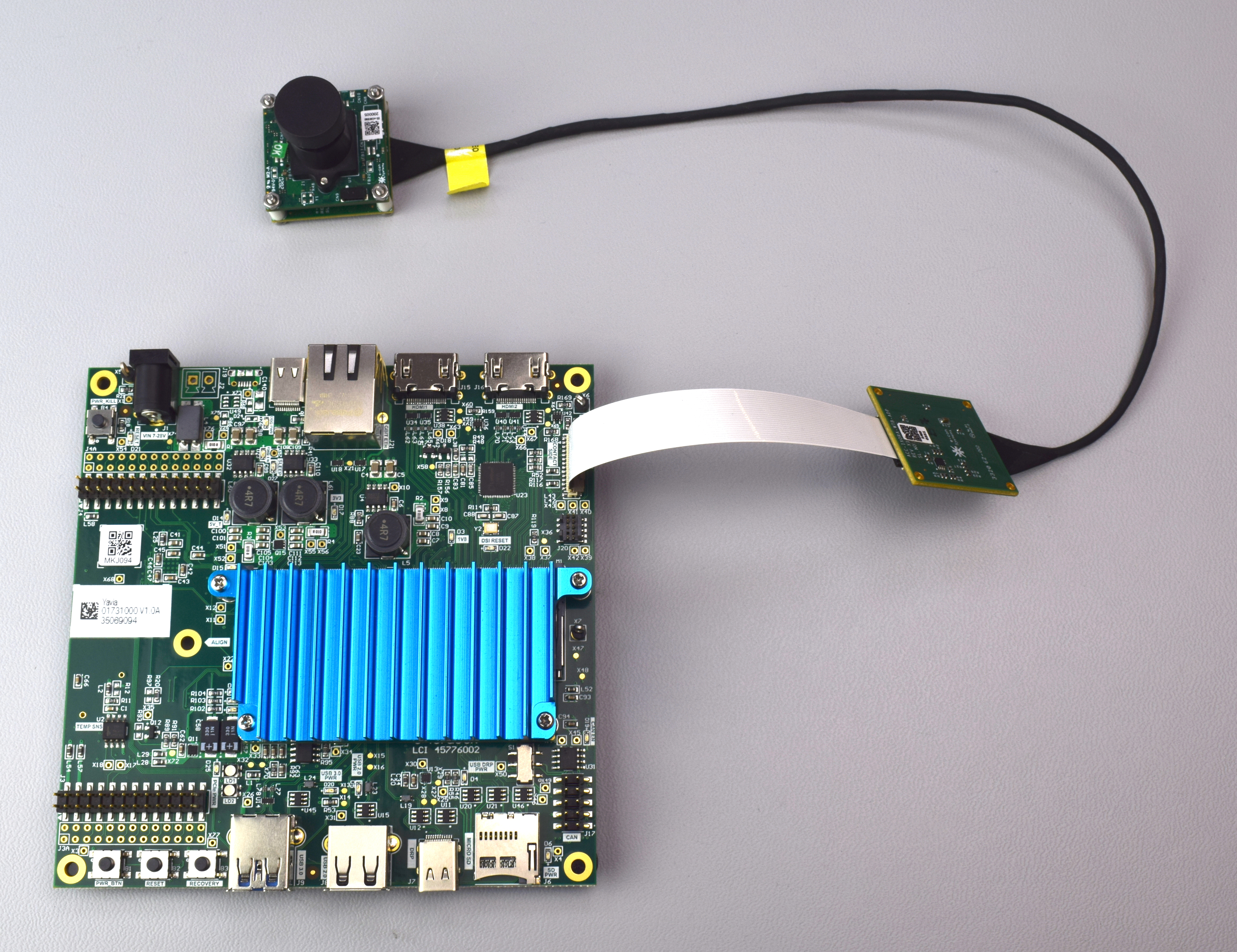
Connection to Yavia Carrier Board
Connect the camera to the Yavia carrier board, as indicated in the figure below. The MIPI-CSI Camera Interface is on connector J14.
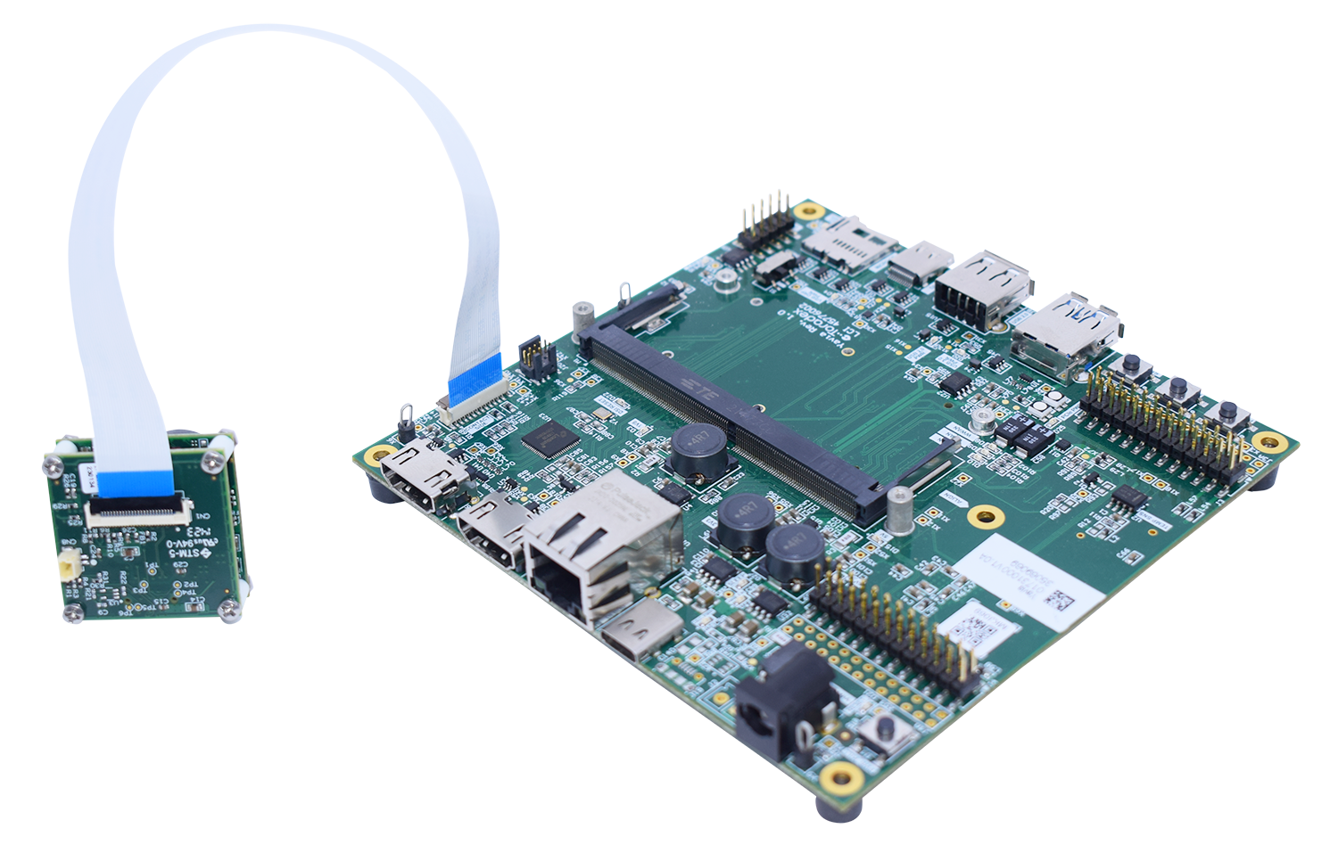
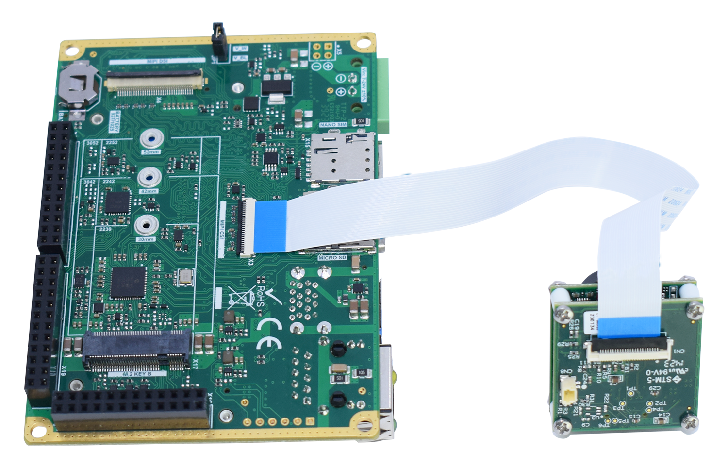
Connection to Mallow Carrier Board
Connect the camera to the Mallow Carrier Board, as indicated in the figure below. The MIPI-CSI Camera Interface is on connector X3.
Add Yocto Project Layer
To enable the camera module, you will need to add a Yocto Project layer provided by Toradex to your Yocto Project environment.
Setup Environment
In order to get your environment setup, read and follow the steps presented in Build a Reference Image with Yocto Project/OpenEmbedded. Stop following the steps prior to starting the build with
bitbake. Once the environment is setup, you can proceed with this article.With your environment setup, you should be in the
builddirectory with the following structure:..
├── build
│ └── conf
│ ├── bblayers.conf
│ ├── local.conf
│ └── templateconf.cfg
├── export
└── layers
├── meta-arm
├── meta-freescale
├── meta-freescale-3rdparty
├── meta-freescale-distro
├── meta-openembedded
├── meta-qt5
├── meta-ti
├── meta-toradex-bsp-common
├── meta-toradex-demos
├── meta-toradex-distro
├── meta-toradex-nxp
├── meta-toradex-ti
├── meta-yocto
└── openembedded-core
Add Layer
2.1. Clone the repository:
$ git clone https://github.com/toradex/meta-toradex-econ.git ../layers/meta-toradex-econ2.2. Add the layer:
$ bitbake-layers add-layer ../layers/meta-toradex-econ/meta-ar0521Build Image
It is recommended to build the reference multimedia image, so that the camera functionality can be easily tested with GStreamer.
RAM UsageIf the build system has many threads or a low amount of RAM, the build can fail due to a lack of RAM.
For information on how to build with reduced RAM usage, see Building with reduced RAM usage.
To build the reference multimedia image, run:
$ bitbake tdx-reference-multimedia-imageInstall the Image
After a successful build, the image will be in the
build/deploy/images/<MACHINE>directory.The article Toradex Easy Installer provides detailed instructions on how to install images using the Toradex Easy installer.
Camera Usage
To test the camera, it is recommended to use a display, in order to be able to visualize the captured image.
The first boot of a camera module with an older firmware installed can take up to 5 minutes. This is the time taken for the camera module to update its firmware.
If the system is reset during this period, the camera module is likely to stop working, due to a corrupted firmware.
The camera might freeze if it is kept operating after many hours. However, this issue can be solved by restarting the device or relaoading the driver.
To reload the camera driver, run the following commands:
echo 2-0042 > /sys/bus/i2c/drivers/ar0521/unbind
echo 2-0042 > /sys/bus/i2c/drivers/ar0521/bind
Connect to the SoM
To follow the next steps, you will need to connect to the SoM after the image is installed. This can be done either via SSH or serial terminal.
Find the Device
To check which /dev/video* is a capture device, the Video4Linux Control (v4l2-ctl) application from the v4l2-utils package can be used.
List the video devices:
# ls /dev/video*
/dev/video0  /dev/video1  /dev/video2
Show information about the capture device on /dev/video2:
# v4l2-ctl -d2 -D
Driver Info:
    Driver name      : mxc-isi-cap
    Card type        : mxc-isi-cap
    Bus info         : platform:32e00000.isi:cap_devic
    Driver version   : 5.15.129
    Capabilities     : 0x84201000
        Video Capture Multiplanar
        Streaming
        Extended Pix Format
        Device Capabilities
    Device Caps      : 0x04201000
        Video Capture Multiplanar
        Streaming
        Extended Pix Format
Media Driver Info:
    Driver name      : mxc-md
    Model            : FSL Capture Media Device
    Serial           :
    Bus info         :
    Media version    : 5.15.129
    Hardware revision: 0x00000000 (0)
    Driver version   : 5.15.129
Interface Info:
    ID               : 0x03000014
    Type             : V4L Video
Entity Info:
    ID               : 0x00000012 (18)
    Name             : mxc_isi.0.capture
    Function         : V4L2 I/O
    Pad 0x01000013   : 0: Sink
        Link 0x02000021: from remote pad 0x100000e of entity 'mxc_isi.0' (Video Pixel Formatter): Data, Enabled
Note that the video device can be in any of the listed video devices. So, check all of them to make sure to use the right one in the pipeline.
To view the video output, run a GStreamer pipeline on the terminal:
# gst-launch-1.0 v4l2src device=/dev/video2 ! video/x-raw,width=1920,height=1080,framerate=65/1 ! fpsdisplaysink text-overlay=false video-sink=waylandsink sync=false -v
Click here to see the Gstreamer command output
Setting pipeline to PAUSED ...
Pipeline is live and does not need PREROLL ...
/GstPipeline:pipeline0/GstFPSDisplaySink:fpsdisplaysink0/GstWaylandSink:waylandsink0: sync = false
Pipeline is PREROLLED ...
Setting pipeline to PLAYING ...
New clock: GstSystemClock
/GstPipeline:pipeline0/GstV4l2Src:v4l2src0.GstPad:src: caps = video/x-raw, width=(int)1920, height=(int)1080, framerate=(fraction)65/1, format=(string)YUY2, interlace-mode=(string)progressive, colorimetry=(string)1:4:5:1
/GstPipeline:pipeline0/GstCapsFilter:capsfilter0.GstPad:src: caps = video/x-raw, width=(int)1920, height=(int)1080, framerate=(fraction)65/1, format=(string)YUY2, interlace-mode=(string)progressive, colorimetry=(string)1:4:5:1
/GstPipeline:pipeline0/GstFPSDisplaySink:fpsdisplaysink0.GstGhostPad:sink.GstProxyPad:proxypad0: caps = video/x-raw, width=(int)1920, height=(int)1080, framerate=(fraction)65/1, format=(string)YUY2, interlace-mode=(string)progressive, colorimetry=(string)1:4:5:1
/GstPipeline:pipeline0/GstFPSDisplaySink:fpsdisplaysink0/GstWaylandSink:waylandsink0.GstPad:sink: caps = video/x-raw, width=(int)1920, height=(int)1080, framerate=(fraction)65/1, format=(string)YUY2, interlace-mode=(string)progressive, colorimetry=(string)1:4:5:1
/GstPipeline:pipeline0/GstFPSDisplaySink:fpsdisplaysink0.GstGhostPad:sink: caps = video/x-raw, width=(int)1920, height=(int)1080, framerate=(fraction)65/1, format=(string)YUY2, interlace-mode=(string)progressive, colorimetry=(string)1:4:5:1
/GstPipeline:pipeline0/GstCapsFilter:capsfilter0.GstPad:sink: caps = video/x-raw, width=(int)1920, height=(int)1080, framerate=(fraction)65/1, format=(string)YUY2, interlace-mode=(string)progressive, colorimetry=(string)1:4:5:1
Redistribute latency...
/GstPipeline:pipeline0/GstFPSDisplaySink:fpsdisplaysink0/GstWaylandSink:waylandsink0: sync = false
/GstPipeline:pipeline0/GstFPSDisplaySink:fpsdisplaysink0: last-message = rendered: 32, dropped: 0, current: 63.06, average: 63.06
/GstPipeline:pipeline0/GstFPSDisplaySink:fpsdisplaysink0: last-message = rendered: 62, dropped: 0, current: 59.09, average: 61.07
/GstPipeline:pipeline0/GstFPSDisplaySink:fpsdisplaysink0: last-message = rendered: 93, dropped: 0, current: 61.06, average: 61.07
/GstPipeline:pipeline0/GstFPSDisplaySink:fpsdisplaysink0: last-message = rendered: 123, dropped: 0, current: 59.09, average: 60.58
/GstPipeline:pipeline0/GstFPSDisplaySink:fpsdisplaysink0: last-message = rendered: 154, dropped: 0, current: 61.06, average: 60.67
^Chandling interrupt.
Interrupt: Stopping pipeline ...
Execution ended after 0:00:03.031688578
Setting pipeline to NULL ...
Total showed frames (158), playing for (0:00:03.031679704), fps (52.116).
Freeing pipeline ...
