Cortex-M and Memory Areas Overview on Toradex SoMs
Introduction
The objective of this article is to provide an overview of Toradex SoMs that feature cores with different architectures, such as the NXP/Freescale i.MX 7 and i.MX 8/8X/8MM/8MP based platforms. Here, you will find general information about the hardware, the ARM Cortex-M cores and memory areas.
Overview
Colibri iMX7
The Cortex-M4 CPU core coexists with the primary Cortex-A7 CPU cores, interconnected to the same peripherals through a shared bus topology. The architecture is depicted in the simplified diagram below.
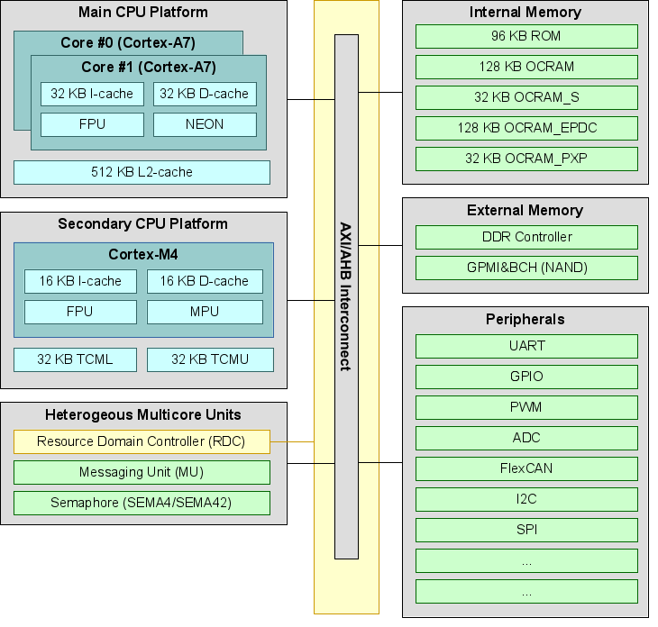
The Cortex-M4 provides Tightly Coupled Memory local memory (TCM), OCRAM areas (SRAM), and DDR3-based main memory. However, there is no internal NOR flash for firmware storage. Instead, the firmware is stored on external mass storage like SD cards or internal eMMC flash. To boot, the i.MX 7 SoC uses the Cortex-A7 core, which then loads a bootloader like U-Boot to execute the firmware on the Cortex-M4. Firmware upgrades can be easily achieved by replacing the binary on the mass storage device. The M4 core can use all DDR memory, but allocation in advance is required. Without SDMA being used by the OS, all OCRAM is free to be used by the M4 core.
Colibri iMX8X
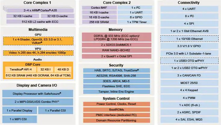
The heterogeneous asymmetric multicore architecture of Toradex modules based on the i.MX8X SoC features the Cortex-M4 CPU core alongside Cortex-A35 primary CPU cores. Both cores have equal access to peripherals via a shared bus topology. The system includes Tightly Coupled Memory (TCM) for the M4 core, which offers low-latency access. For larger memory requirements, the system DRAM is accessible to the M4 core. Firmware is stored on mass storage devices like SD-cards or internal eMMC flash, and U-Boot needs to be configured to load and execute the M4 firmware.
Verdin iMX8M Mini
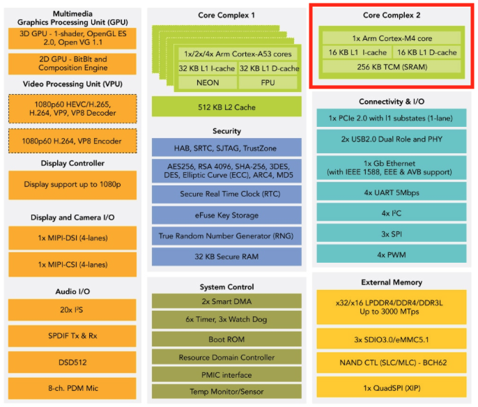
The Verdin iMX8M Mini features a heterogeneous multicore architecture, with the Cortex-M4 CPU core alongside the Cortex-A53 primary CPU cores. Both core complexes have equal access to peripherals through a shared bus topology. The system includes Tightly Coupled Memory (TCM) for the M4 core, offering low-latency access. For larger memory requirements, the system DRAM is accessible to the M4 cores. Firmware is stored on mass storage devices like SD cards or internal eMMC flash. Both booting an Execution-In-Place (XIP) and non XIP image are supported from Serial NOR Flash. For XIP boot, the image has to be built for FlexSPI address space and for non XIP the image can be built to execute from Internal RAM In any case, U-Boot needs to be configured to load and execute the M4 firmware.
Verdin iMX8M Plus
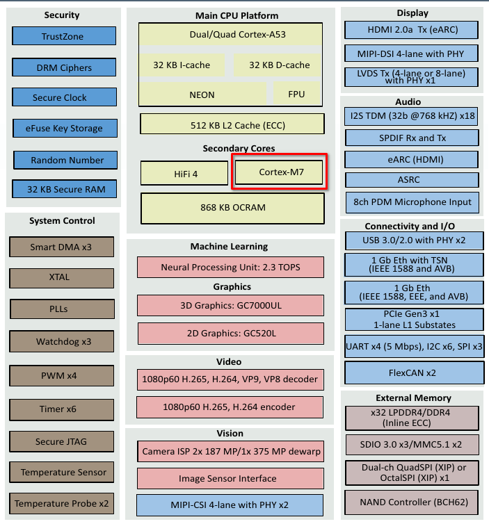
The Verdin iMX8M Plus features a heterogeneous multicore architecture, with the Cortex-M7 core alongside with 4 Cortex-A53 primary CPU cores, which have equal access to peripherals through a shared bus topology. The system includes Tightly Coupled Memory (TCM) for the M7 core, offering low-latency access. Firmware is stored on mass storage devices like SD cards or internal eMMC flash. Both booting an Execution-In-Place (XIP) and non XIP image are supported from Serial NOR Flash. For XIP boot, the image has to be built for FlexSPI address space and for non XIP the image can be built to execute from Internal RAM In any case, U-Boot needs to be configured to load and execute the M7 firmware.
Apalis iMX8
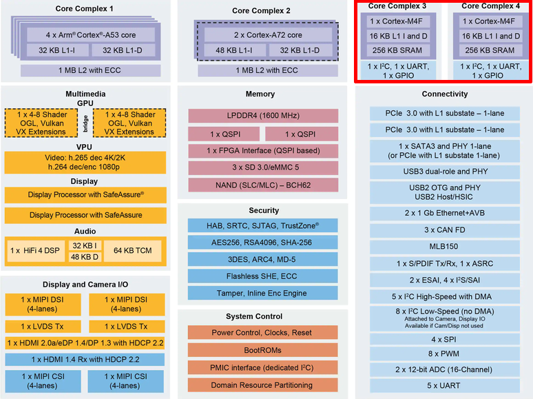
The Apalis iMX8QM features a heterogeneous multicore architecture with 2 Cortex-M4 CPU cores alongside Cortex-A53/A72 primary CPU cores. Both core complexes have equal access to peripherals through a shared bus topology. The system includes Tightly Coupled Memory (TCM) for the M4 cores, offering low-latency access. For larger memory requirements, the system DRAM is accessible to the M4 cores. Firmware is stored on mass storage devices like SD cards or internal eMMC flash and U-Boot needs to be configured to load and execute the M4 firmware. Booting non-XIP image is supported from the serial flash, so the image can be built to execute from the DDR or OCRAM.
Memory Areas
The two CPU platforms (Cortex-A and Cortex-M) use a different memory layout to access individual sub systems. The tables below list some important areas and their memory location for each of the cores side by side. The full list can be found in the reference manual from each SoC vendor.
Colibri iMX7
The Cortex-M4 CPU has two buses connected to the main interconnect (modified Harvard architecture). One bus is meant to fetch data (system bus) whereas the other bus is meant to fetch instructions (code bus). To get optimal performance, the program code should be located and linked for a region which is going to be fetched through the code bus, while the data area (e.g. bss or data section) should be located in a region which is fetched through the system bus. There are multiple example linker files in the platform/devices/MCIMX7D/linker/ sub directory which can be used and/or modified. All example firmware below use the MCIMX7D_M4_tcm.ld linker file (TCML region for code, and the TCMU region for data).
| Region | Size | Cortex-A7 | Cortex-M4 (System Bus) | Cortex-M4 (Code Bus) | GCC Linker file |
|---|---|---|---|---|---|
| DDR Address | 2048MB (less for M4) | 0x8000_0000-0xFFFF_FFFF | 0x8000_0000-0xDFFF_FFFF | 0x1000_0000-0x1FFE_FFFF | MCIMX7D_M4_ddr.ld |
| OCRAM_PXP | 32KB | 0x0094_0000-0x0094_7FFF | 0x2024_0000-0x2024_7FFF | 0x0094_0000-0x0094_7FFF | |
| OCRAM_EPDC | 128KB | 0x0092_0000-0x0093_FFFF | 0x2022_0000-0x2023_FFFF | 0x0092_0000-0x0093_FFFF | MCIMX7D_M4_ocram.ld |
| OCRAM | 128KB | 0x0090_0000-0x0091_FFFF | 0x2020_0000-0x2021_FFFF | 0x0090_0000-0x0091_FFFF | MCIMX7D_M4_ocram.ld |
| TCMU | 32KB | 0x0080_0000-0x0080_7FFF | 0x2000_0000-0x2000_7FFF | _ _ | MCIMX7D_M4_tcm.ld |
| TCML | 32KB | 0x007F_8000-0x007F_FFFF | _ _ | 0x1FFF_8000-0x1FFF_FFFF | MCIMX7D_M4_tcm.ld |
| OCRAM_S | 32KB | 0x0018_0000-0x0018_7FFF | 0x0018_0000-0x0018_7FFF | 0x0000_0000-0x0000_7FFF | |
| Boot ROM | 96KB | 0x0000_0000-0x0001_7FFF | 0x2002_0000-0x2003_7FFF |
Colibri iMX8X
The Cortex-M4 CPU has two buses connected to the main interconnect (modified Harvard architecture). One bus is meant to fetch data (system bus) whereas the other bus is meant to fetch instructions (code bus). To get optimal performance, the program code should be located and linked for a region which is going to be fetched through the code bus, while the data area (e.g. bss or data section) should be located in a region which is fetched through the system bus. The TCML and TCMU regions can be accessed with zero wait-states and thus provides massively better performance than DRAM, even if it is cached. Therefore it is advisable to place all code and data in the TCM whenever possible.
| Region | Size | Cortex-A35 | M4 (Code Bus) | M4 (System Bus) |
|---|---|---|---|---|
| DDR | 2GB(*1) | 0x8000_0000-0xFFFF_FFFF | 0x0010_0000-0x1BFF_FFFF | 0x8000_0000-0xDFFF_FFFF |
| TCML | 128KB | 0x34FE_0000-0x34FF_FFFF | 0x1FFE_0000-0x1FFF_FFFF | |
| TCMU | 128KB | 0x3500_0000-0x3501_FFFF | 0x2000_0000-0x2001_FFFF |
(*1): Full DRAM range is 0x8_0000_0000 - 0xB_FFFF_FFFF. Only a part of the DRAM is accessible by the M4 cores.
Verdin iMX8M Mini
The Cortex-M4 CPU has two buses connected to the main interconnect (modified Harvard architecture). One bus is meant to fetch data (system bus) whereas the other bus is meant to fetch instructions (code bus). To get optimal performance, the program code should be located and linked for a region which is going to be fetched through the code bus, while the data area (e.g. bss or data section) should be located in a region which is fetched through the system bus. The TCML and TCMU regions can be accessed with zero wait-states and thus provides massively better performance than DRAM, even if it is cached. Therefore it is advisable to place all code and data in the TCM whenever possible.
| Region | Size | Cortex-A53 | M4-0 |
|---|---|---|---|
| DDR Address | 2GB(*1) | 0x0000_0000-0x3FFF_FFFF | 0x4000_0000-0xBFFF_FFFF |
| TCML for M4 | 128KB | 0x007E_0000-0x007F_FFFF | 0x1FFE_0000-0x1FFF_FFFF |
| TCMU for M4 | 128KB | 0x0080_0000-0x0081_FFFF | 0x2000_0000-0x2001_FFFF |
(*1): Full DRAM range is 0x1_0000_0000 - 0x2_FFFF_FFFF. Only a part (2048MB) of the DRAM is accessible by the M4 cores.
Verdin iMX8M Plus
The Cortex-M7 CPU has two buses connected to the main interconnect (modified Harvard architecture). One bus is meant to fetch data (system bus) whereas the other bus is meant to fetch instructions (code bus). To get optimal performance, the program code should be located and linked for a region which is going to be fetched through the code bus, while the data area (e.g. bss or data section) should be located in a region which is fetched through the system bus. The TCM regions can be accessed with zero wait-states and thus provides massively better performance than DRAM, even if it is cached. Therefore it is advisable to place all code and data in the TCM whenever possible.
| Region | Size | Cortex-A53 | M7-0 |
|---|---|---|---|
| DDR Address | 2GB(*1) | 0x4000_0000-0xBFFF_FFFF | 0x4000_0000-0xBFFF_FFFF |
| DTCM for M7 | 128KB | 0x0080_0000-0x0081_FFFF | 0x2000_0000-0x2001_FFFF |
| ITCM for M7 | 128KB | 0x007E_0000-0x007F_FFFF | 0x0000_0000-0x0001_FFFF |
(*1): Full DRAM range is 0x4000_0000 - 0x2_3FFF_FFFF (8192MB). Only the initial 2048MB of the DRAM are accessible by the M7 core.
Apalis iMX8
The Cortex-M4 CPU has two buses connected to the main interconnect (modified Harvard architecture). One bus is meant to fetch data (system bus) whereas the other bus is meant to fetch instructions (code bus). To get optimal performance, the program code should be located and linked for a region which is going to be fetched through the code bus, while the data area (e.g. bss or data section) should be located in a region which is fetched through the system bus. The TCML and TCMU regions can be accessed with zero wait-states and thus provides massively better performance than DRAM, even if it is cached. Therefore it is advisable to place all code and data in the TCM whenever possible.
| Region | Size | Cortex-A53/A72 | M4-0 (Code Bus) | M4-0 (System Bus) | M4-1 (Code Bus) | M4-1 (System Bus) |
|---|---|---|---|---|---|---|
| DDR Address | 2GB(*1) | 0x8000_0000-0xFFFF_FFFF | 0x0010_0000-0x1BFF_FFFF | 0x8000_0000-0xDFFF_FFFF | 0x0010_0000-0x1BFF_FFFF | 0x8000_0000-0xDFFF_FFFF |
| TCML for M4-0 | 128KB | 0x34FE_0000-0x34FF_FFFF | 0x1FFE_0000-0x1FFF_FFFF | N/A | N/A | |
| TCMU for M4-0 | 128KB | 0x3500_0000-0x3501_FFFF | 0x2000_0000-0x2001_FFFF | N/A | N/A | |
| TCML for M4-1 | 128KB | 0x38FE_0000-0x38FF_FFFF | N/A | N/A | 0x1FFE_0000-0x1FFF_FFFF | |
| TCMU for M4-1 | 128KB | 0x3900_0000-0x3901_FFFF | N/A | N/A | 0x2000_0000-0x2001_FFFF |
(*1): Full DRAM range is 0x8_0000_0000 - 0xB_FFFF_FFFF. Only a part of the DRAM is accessible by the M4 cores