Get Started with Hardware
Developer resources and documentations
Software and Services
Get latest software updates and information
BSP & Yocto Projects
BSP Layers and Reference Images Linux Application Development Real-Time OS BSP Issue Tracker
Toradex Community
Join Toradex Community! Helps you resolve your queries, discuss, share and help. We invite you to be a part of this ever-growing community constituted by our embedded enthusiasts.
Join Now!
Our Partners
We know that you need more than just our Computer on Modules for your embedded projects. Our network of partners can help you in your product development for both hardware and software requirements.


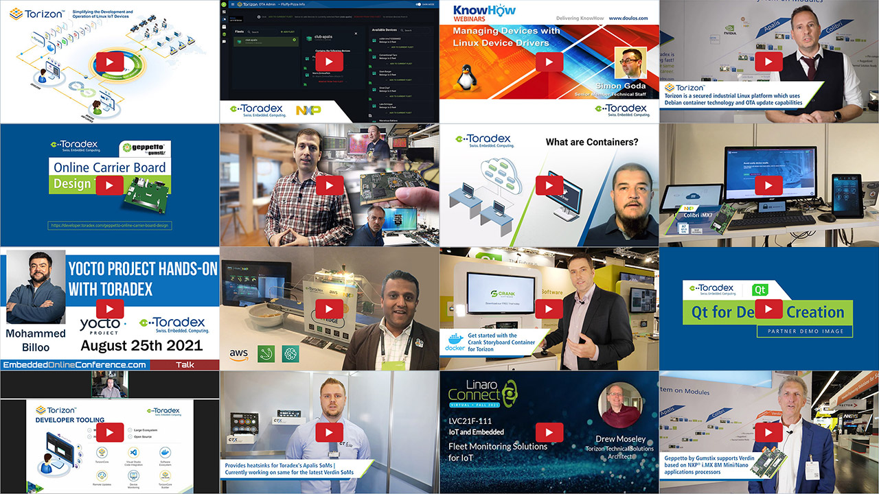
Videos
The Toradex video channel aims at showcasing interesting demo videos, handy tutorials, webinar recordings, customer feedback, and much more - based on Toradex's product portfolio and value offerings.
Subscribe to the Toradex YouTube channel to stay updated with our latest videos.