First Steps with Arducam CSI Camera Module 5MP OV5640
Introduction
This article provides information on how to start working with the CSI Camera Module based on the OV5640 image sensor from Arducam.
The following topics will be covered:
How to Use Video Streams on Linux - Video4Linux & GStreamer
For details about using Video4Linux and GStreamer tools to interact with cameras and collect video frames, see Cameras on Toradex System on Modules.
Features
The OV5640 is a high-performance CMOS image sensor designed for a wide range of imaging applications. It offers a combination of high resolution,advanced imaging features, and versatility, making it a popular choice for mobile and embedded camera systems.
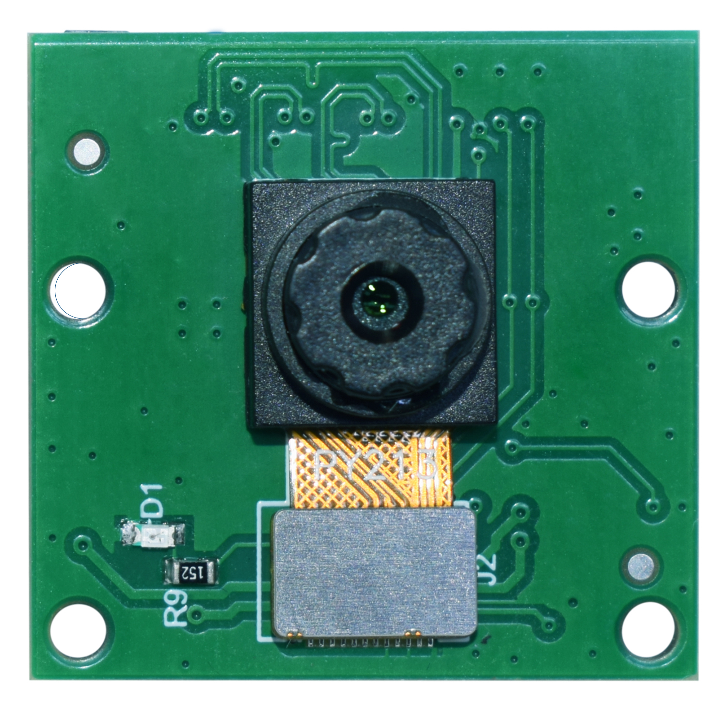
Arducam has designed the OV5640 camera module and integrated it into the Toradex carrier boards via the MIPI protocol. The camera circuit board, after being improved by the Arducam technical team, has reached a mini size of 24x25mm, which makes it easier for visual projects to be applied in narrow spaces with limited size.
Sensor Features:
- Image Sensor: OV5640 from OmniVision
- Still Resolution: 5Megapixels
- Interface: MIPI CSI-2
- Output Format: 8-/10-bit RGB RAW, RGB, YUV, JPEG
- Max Pixel Array: 2592 x 1944 pixels
- Sensor image area: 6.287mm x 4.712 mm (7.9mm diagonal)
- Pixel Size 1.4μm x 1.4μm
- Optical Size: 1/4"
Lens Features:
- IR Sensitivity: Integral IR-cut Filter, visible light only
- Focal length: 4.22mm
- Aperture: F2.0 +-5%
- Field of View (FOV): 84.2°(D)×71.7°(H)×57°(V)
- Lens Mount: Stock Lens
Datasheets
Arducam CSI Camera Module OV5640 Datasheet
Hardware Setup
What I need to order
You can have the Arducam OV5640 CSI Camera Module working with specific Toradex computers on modules and carrier boards. See the compatible products.
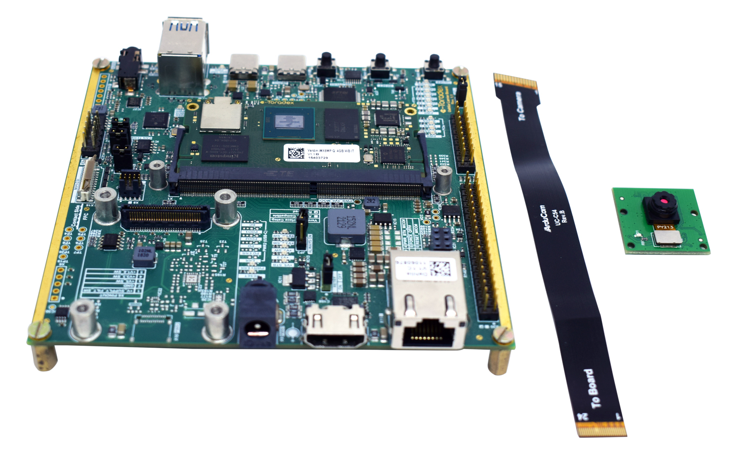
Besides the Module and the Carrier Board, you will need to order:
- The Arducam OV5640 Camera Module;
- The flat cable for connecting the Camera Module to the Carrier Board.
Where do I order
You can order the Toradex computer on Modules and the carrier boards online in the Toradex Webshop.
You can order the Arducam Camera Module and the needed accessories on the Arducam Shop.
Please refer to the instructions below for connecting the camera module to your specific carrier board.
Cable Connection
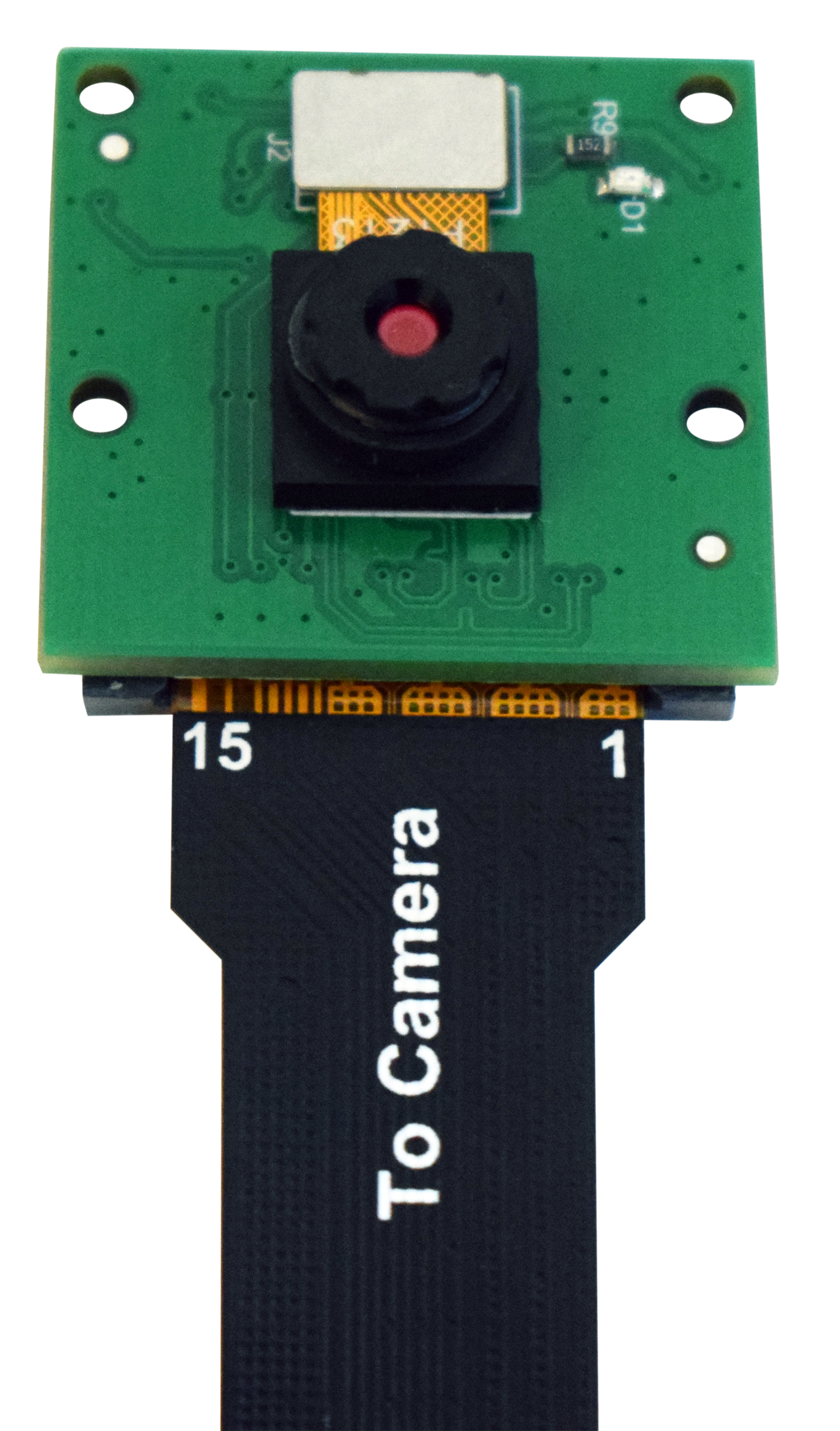
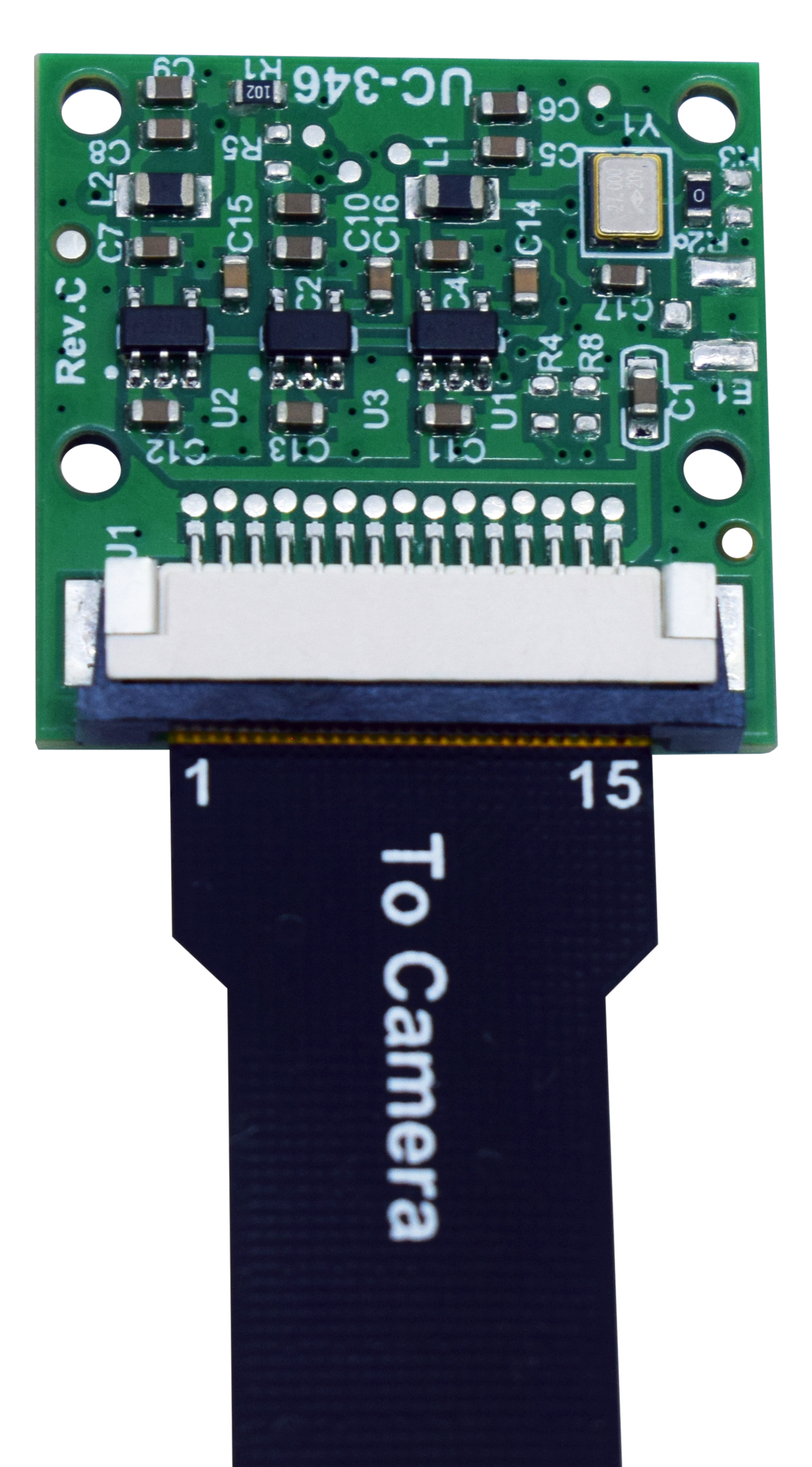
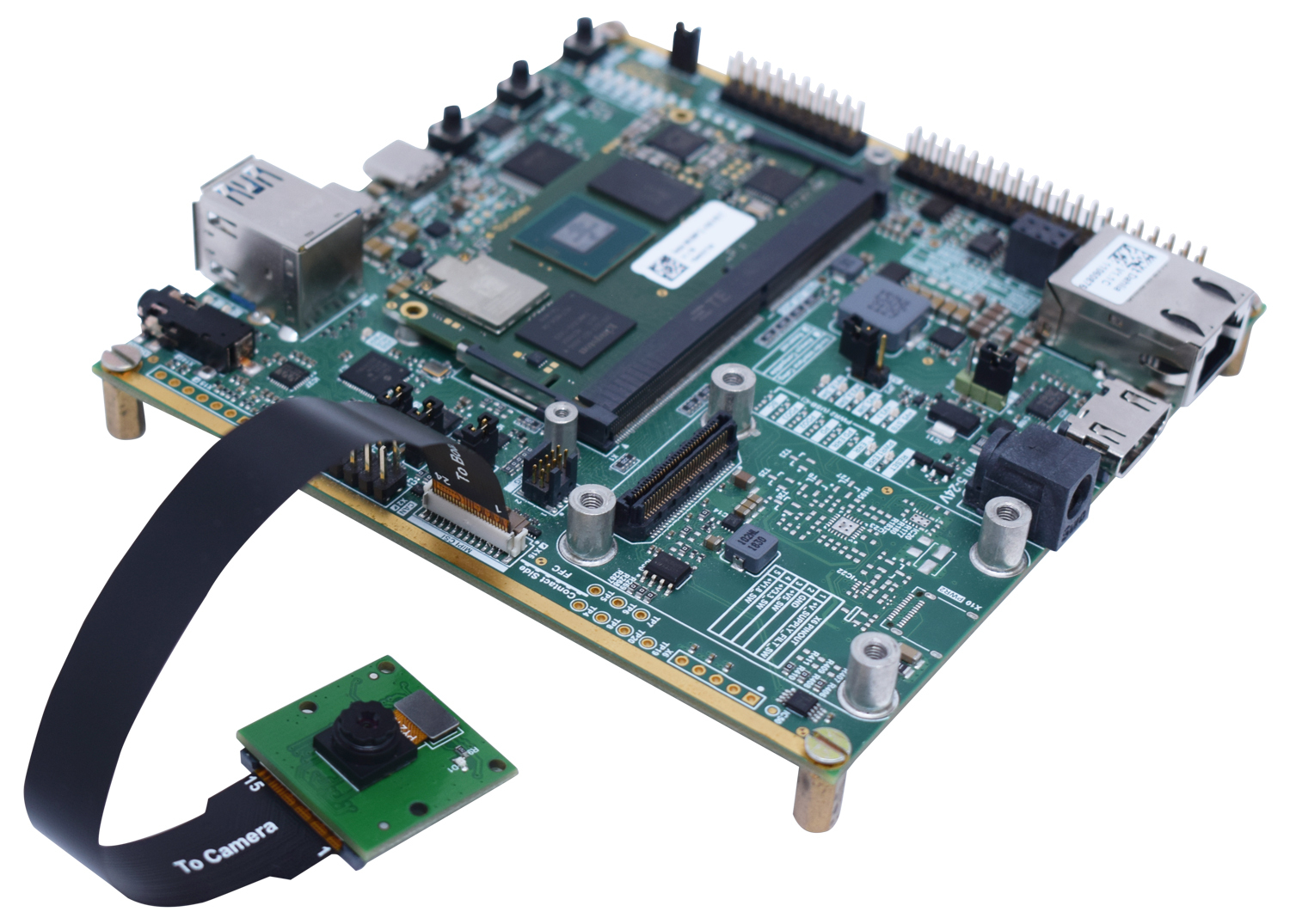
Connect the flat cable to the camera module as shown in the following pictures:
Please disconnect any power and USB cables from the board before connecting the flat cable to the MIPI-CSI bus to avoid any damage to the camera!
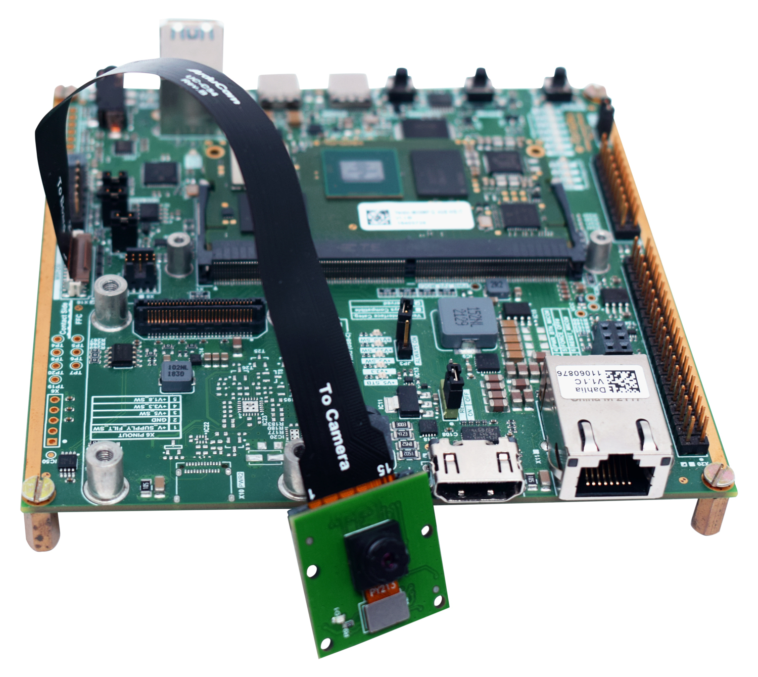
Connection to Dahlia Carrier Board
Connect the camera to the Dahlia Carrier Board, assuring that the flat cable contacts are on the correct side, as indicated in the figures below.
- For the Dahlia Carrier Board, the MIPI-CSI Camera interface is on connector X16.
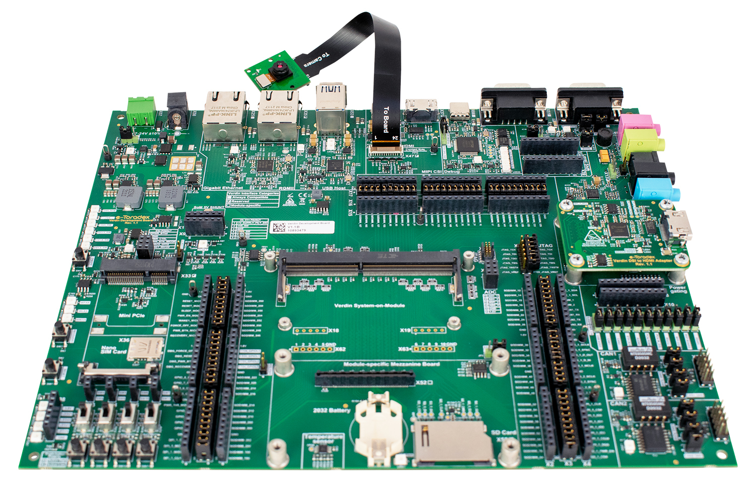
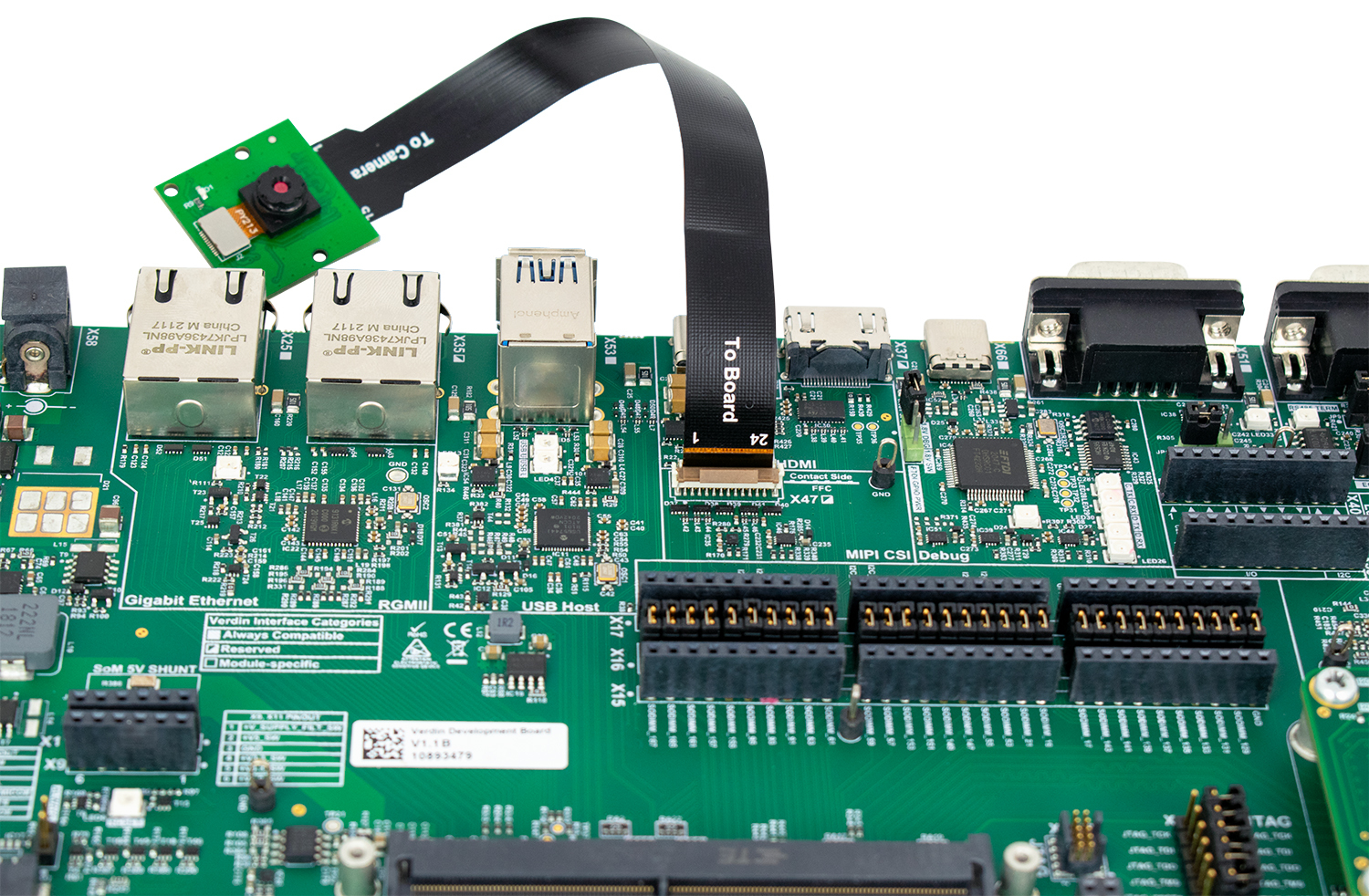
Connection to Verdin Development Board
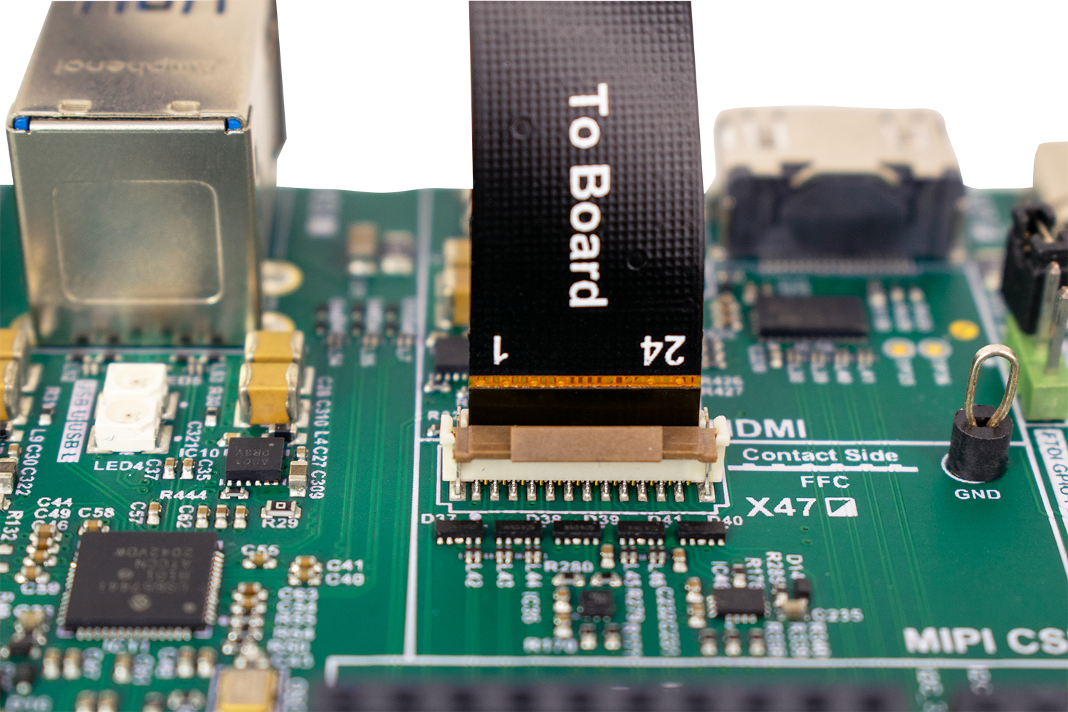
Connect the camera to the Verdin Development Board, assuring that the flat cable contacts are on the correct side, as indicated in the figures below.
- For the Verdin Development Board, the MIPI-CSI Camera interface is on connector X47.
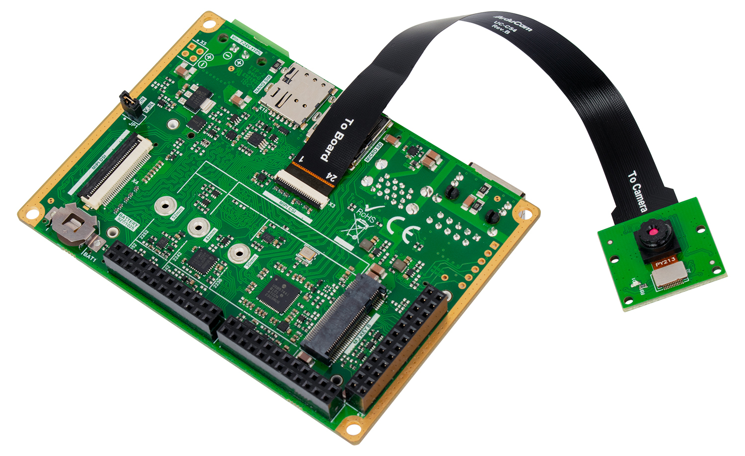
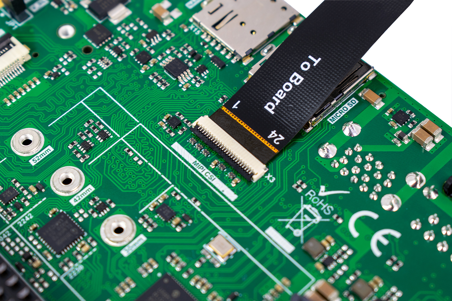
Connection to Mallow Carrier Board
Connect the camera to the Mallow Carrier Board, assuring that the flat cable contacts are on the correct side, as indicated in the figures below.
- For the Mallow Carrier Board, the MIPI-CSI Camera interface is on connector X3.
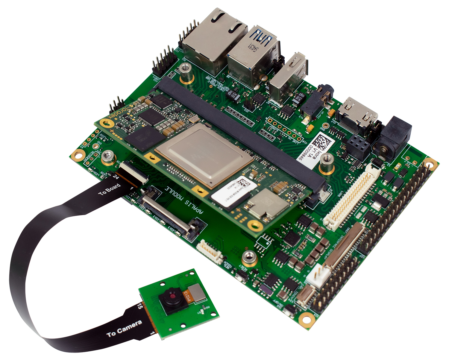
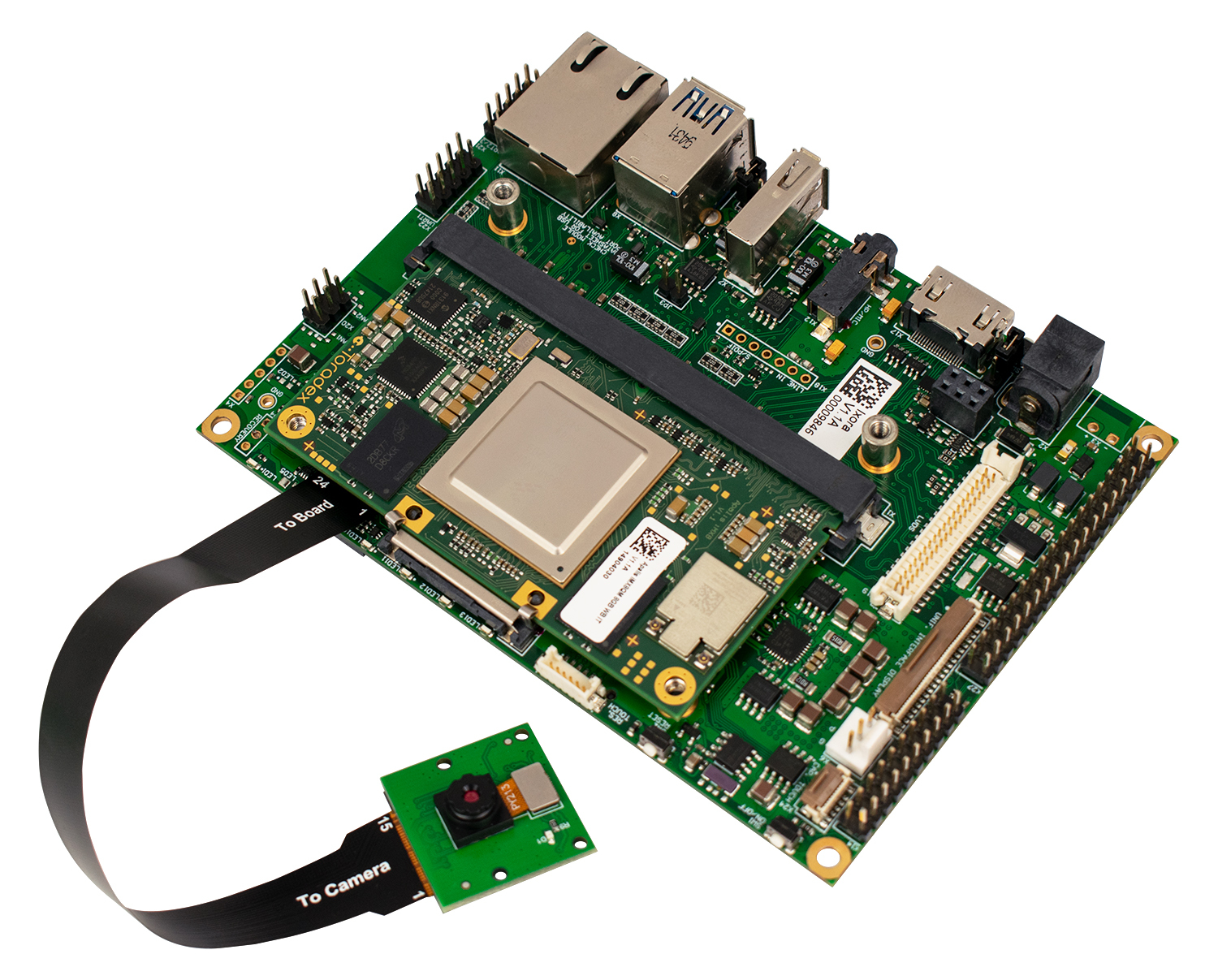
Connection to Ixora Carrier Board
Connect the camera to the Ixora Carrier Board, assuring that the flat cable contacts are on the correct side, as indicated in the figures below.
- For the Ixora Carrier Board, the the MIPI-CSI Camera interface is on connector X28.
The flat cable (used to connect the carrier board and the camera adaptor) is fragile. If your camera does not work, make sure to test the cable connections on the flat cable.
Compatible Products
Hardware
The Arducam CSI Camera Module 5MP OV5640 is sold together with a connector cable.
The following Toradex carrier boards that support the MIPI CSI-2 interface connect to the camera kits out-of-the-box, hardware-wise:
This camera module is supported for the following SoMs:
Software
Software support for this camera is fully integrated from BSP version 7.
To integrate the camera on the software side, you need to apply an device tree overlay to the image, as shown in the next sections.
Camera Usage
We recommend using a display to be able to visualize the captured image during camera testing.
Connect to the SoM
To follow the next steps, you will also need to connect to the Device after the image is installed. You can do it either via SSH or serial terminal
Select and Apply the Device Tree Overlay:
Once you are connected to the board, check which overlays are currently applied:
# cat /boot/overlays.txt
The output shows the contents of the fdt_overlays variable, as the example:
# fdt_overlays=verdin-imx8mp_hdmi_overlay.dtbo verdin-imx8mp_dsi-to-hdmi_overlay.dtbo verdin-imx8mp_spidev_overlay.dtbo
Edit the /boot/overlays.txt file, appending the desired overlay filename to the fdt_overlays variable.
-
For the supported Verdin Family SoMs:
verdin-[SoM name]_ov5640-27mhz_overlay.dtbo. -
For the Apalis iMX8:
apalis-imx8_ov5640-27mhz_overlay.dtb
In our example using Verdin iMX8MP, the content of the /boot/overlays.txt file should be:
# fdt_overlays=verdin-imx8mp_hdmi_overlay.dtbo verdin-imx8mp_dsi-to-hdmi_overlay.dtbo verdin-imx8mp_spidev_overlay.dtbo verdin-imx8mp_ov5640-27mhz_overlay.dtbo
Reboot the board to apply the overlay:
# reboot
At the beginning of the boot process, you can confirm that the overlay was applied successfully in the messages:
Found U-Boot script /boot.scr
5974 bytes read in 1 ms (5.7 MiB/s)
## Executing script at 50280000
Loading DeviceTree: imx8mp-verdin-wifi-dev.dtb
87774 bytes read in 2 ms (41.9 MiB/s)
152 bytes read in 1 ms (148.4 KiB/s)
Working FDT set to 50200000
Applying Overlay: verdin-imx8mp_hdmi_overlay.dtbo
2219 bytes read in 2 ms (1.1 MiB/s)
Applying Overlay: verdin-imx8mp_dsi-to-hdmi_overlay.dtbo
4099 bytes read in 1 ms (3.9 MiB/s)
Applying Overlay: verdin-imx8mp_spidev_overlay.dtbo
561 bytes read in 1 ms (547.9 KiB/s)
Applying Overlay: verdin-imx8mp_ov5640-27mhz_overlay.dtbo
3217 bytes read in 1 ms (3.1 MiB/s)
8106902 bytes read in 33 ms (234.3 MiB/s)
Find the Device
To check which /dev/video* is a capture device, the Video4Linux Control (v4l2-ctl) application from the v4l2-utils package can be used.
List the video devices:
# ls /dev/video*
/dev/video0  /dev/video1  /dev/video2  /dev/video3
Show information about the capture device on /dev/video3:
# v4l2-ctl -d3 -D
Driver Info:
        Driver name      : mxc-isi-cap_v1
        Card type        : mxc-isi-cap_v1
        Bus info         : platform:32e00000.isi:cap_devic
        Driver version   : 6.6.23
        Capabilities     : 0x84201000
                Video Capture Multiplanar
                Streaming
                Extended Pix Format
                Device Capabilities
        Device Caps      : 0x04201000
                Video Capture Multiplanar
                Streaming
                Extended Pix Format
Note that the video device can be in any of the listed video devices. So, check all of them to make sure to use the right one in the pipeline.
To view the video output, run the instructions according to your SoM:
# gst-launch-1.0 -v v4l2src device=/dev/video3 ! video/x-raw ! videoconvert ! waylandsink
# gst-launch-1.0 -v v4l2src device=/dev/video2 ! video/x-raw ! videoconvert ! waylandsink
The media pipeline is already set up by the device tree settings. However, you must configure the video source format and has to force a matching format in the gstreamer pipeline.
# media-ctl --set-v4l2 '"ov5640 4-003c":0 [fmt:YUYV8_1X16/640x480@1/30]'
# media-ctl --set-v4l2 '"cdns_csi2rx.30101000.csi-bridge":0 [fmt:YUYV8_1X16/640x480]'
# media-ctl --set-v4l2 '"30102000.ticsi2rx":0 [fmt:YUYV8_1X16/640x480]'
After that, start the Gstreamer pipeline with the following command:
# gst-launch-1.0 v4l2src device=/dev/video0 ! video/x-raw,width=640,height=480, format=YUY2 ! waylandsink sync=false -v
The media pipeline is already set up by the device tree settings. However, you must configure the video source format and has to force a matching format in the gstreamer pipeline.
# media-ctl --set-v4l2 '"ov5640 4-003c":0 [fmt:YUYV8_1X16/640x480@1/30]'
# media-ctl --set-v4l2 '"cdns_csi2rx.30101000.csi-bridge":0 [fmt:YUYV8_1X16/640x480]'
# media-ctl --set-v4l2 '"30102000.ticsi2rx":0 [fmt:YUYV8_1X16/640x480]'
After that, start the Gstreamer pipeline with the following command:
# gst-launch-1.0 -v v4l2src device=/dev/video3 ! video/x-raw ! videoconvert ! waylandsink
# gst-launch-1.0 -v v4l2src device=/dev/video4 ! video/x-raw ! videoconvert ! waylandsink
Click here to see a sample of the Gstreamer command output. This may vary depending on the used SoM.
# gst-launch-1.0 -v v4l2src device=/dev/video3 ! video/x-raw ! videoconvert ! waylandsink
Setting pipeline to PAUSED ...
Pipeline is live and does not need PREROLL ...
Pipeline is PREROLLED ...
Setting pipeline to PLAYING ...
New clock: GstSystemClock
/GstPipeline:pipeline0/GstV4l2Src:v4l2src0.GstPad:src: caps = video/x-raw, format=(string)YUY2, width=(int)1920, height=(int)1080, framerate=(fraction)30/1, interlace-mode=(string)progressive, colorimetry=(string)1:4:5:1
/GstPipeline:pipeline0/GstCapsFilter:capsfilter0.GstPad:src: caps = video/x-raw, format=(string)YUY2, width=(int)1920, height=(int)1080, framerate=(fraction)30/1, interlace-mode=(string)progressive, colorimetry=(string)1:4:5:1
/GstPipeline:pipeline0/GstVideoConvert:videoconvert0.GstPad:src: caps = video/x-raw, format=(string)YUY2, width=(int)1920, height=(int)1080, framerate=(fraction)30/1, interlace-mode=(string)progressive, colorimetry=(string)1:4:5:1
/GstPipeline:pipeline0/GstWaylandSink:waylandsink0.GstPad:sink: caps = video/x-raw, format=(string)YUY2, width=(int)1920, height=(int)1080, framerate=(fraction)30/1, interlace-mode=(string)progressive, colorimetry=(string)1:4:5:1
/GstPipeline:pipeline0/GstVideoConvert:videoconvert0.GstPad:sink: caps = video/x-raw, format=(string)YUY2, width=(int)1920, height=(int)1080, framerate=(fraction)30/1, interlace-mode=(string)progressive, colorimetry=(string)1:4:5:1
/GstPipeline:pipeline0/GstCapsFilter:capsfilter0.GstPad:sink: caps = video/x-raw, format=(string)YUY2, width=(int)1920, height=(int)1080, framerate=(fraction)30/1, interlace-mode=(string)progressive, colorimetry=(string)1:4:5:1
Redistribute latency...
0:00:12.3 / 99:99:99.
Having trouble?
Please contact our technical support. Various options for technical support are mentioned in the article below.
