First Steps with Capacitive Touch Display 7" Parallel
Introduction
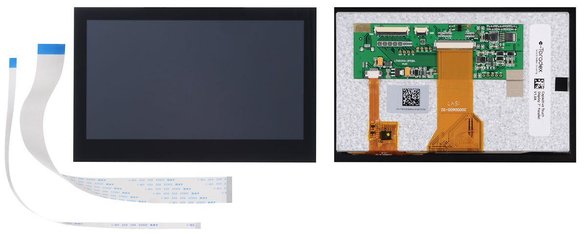
This article provides information on how to start working with the Capacitive Touch Display 7" Parallel, which includes how to set up the hardware (wiring), install and configure the necessary drivers for a touch demo.
Getting Started
What I need to order
The Capacitive Touch Display 7" Parallel can be ordered with many Toradex computer on modules and carrier boards. See the compatible products.
Where do I order
All the products can be ordered online in the Toradex Webshop.
Cable Connection
When connecting the display to any of our carrier boards, make sure that pin 1 of the display is connected to pin 1 of the board. Due to the nature of the FFC connectors, it is possible to invert the pinout and possibly damage the display and/or carrier board.
- The connectors available on the display do have contacts on the top and bottom side.
- Our Iris & Viola Carrier Boards also have contacts on the top and bottom side of the FFC connector.
- The FFC connectors on the Colibri Evaluation Board, Ixora carrier board, and Apalis Evaluation Board have only contacts on the side towards the board edge.
Also, be careful with the brown levers on the connectors. They are very delicate and can easily break.
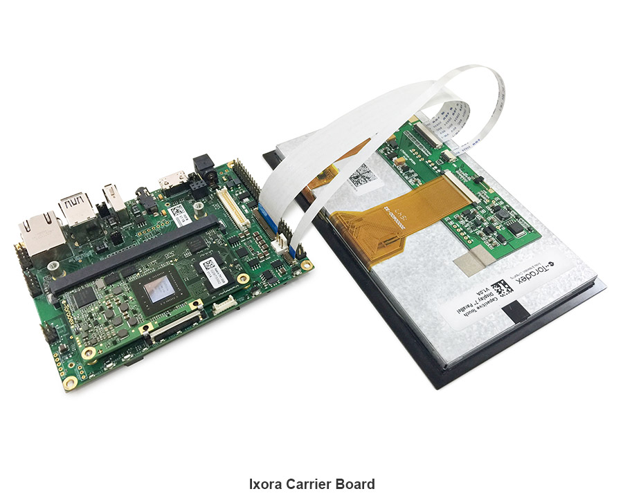
Please have a look at the pictures in the following section which show how to connect the display with our carrier boards & Evaluation boards:
Connections on Ixora V1.1 and Newer, Aster, Iris V2.0 and Newer
At present these carrier boards support a Capacitive Touch Interface Connector with our Capacitive Touch Display 7" Parallel.
Please refer to the below images for connecting the display to our Ixora Carrier Board (V1.1 and above, for V1.0 the Capacitive Touch Adapter is needed) & Aster Carrier Board.
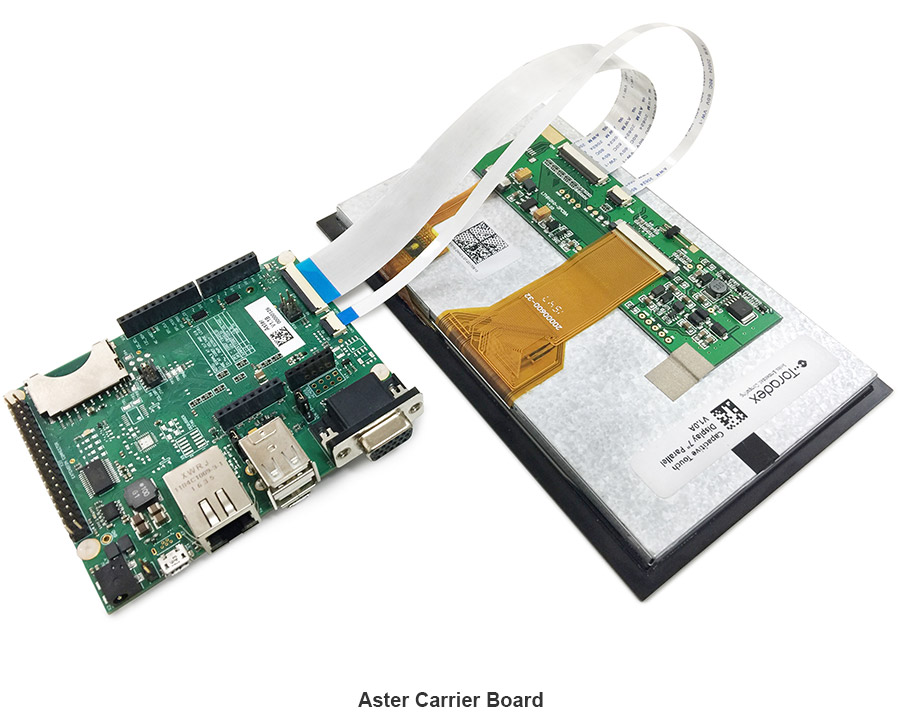
We do not have pictures to illustrate the connection of Iris V2.0, but the connector and pinout are the same. Use the pictures above as reference.
Connections on Ixora V1.0, Iris V1.1 and Older, Viola, Colibri Evalutation Board, Apalis Evaluation board
For other carrier boards or evaluation boards like Iris (V1.1A and V1.1B, for V2.0 or above Capacitive Touch Adapter is not needed), Viola, Colibri Evaluation Board, Apalis Evaluation Board, one can use the Capacitive Touch Adapter as the capacitive touch connector is not yet available on these carrier boards. All connection details are available in the Capacitive Touch Adapter datasheet.
Installation on Embedded Linux
Torizon OS
On Torizon OS, Toradex deploys pre-compiled and ready-to-use device tree overlays for this display, including the touch panel, inherited from the BSP layers. Enabling them for evaluation can be done with few commands. Learn how to do it on Setting up Displays with Torizon.
Reference Images for Yocto Project
On the Linux BSP, Toradex deploys pre-compiled and ready-to-use device tree overlays for this display, including the touch panel. This enables you to evaluate it with few commands and very fast. Learn how to do it on Device Tree Overlays (Linux).
BSP 2.8 - Ångström
Click the tab that corresponds to your module:
Colibri VF50/VF61
The following instructions will work only using the dedicated Capacitive Interface Connector (X24 at Ixora Carrier Board and X3 at Aster Carrier Board)
Resolution
To configure the correct display resolution set the correct panel in the device tree.
setenv fdt_fixup 'fdt addr ${fdt_addr_r} && fdt resize && ${fdt_resolution} && ${fdt_touch}'
setenv fdt_resolution 'fdt set /panel compatible "logic,lt161010-2nhc"'
saveenv
Connection with Capacitive Touch Adapter
These instructions are not required if you are not using the Capacitive Touch Adapter.
Due to wiring differences, this needs further device tree customizations. For compatibility across carrier board/s PWM_B/PWM_C pins are used as pen-down and reset interrupt, so the PWM functionality on these pins has to be disabled and the relevant GPIO functionality enabled and assigned to the touch driver.
On Vybrid based devices the two PWM instances, PWM_B/PWM_C need to be disabled in the device tree. Modify the device tree, re-compile and flash the module, according to the following instructions:
Colibri VF Instructions
Change the device tree according to the patch below:
diff --git a/arch/arm/boot/dts/vf-colibri-eval-v3.dtsi b/arch/arm/boot/dts/vf-colibri-eval-v3.dtsi
index dc703043d3ac..0ae6dc25b6ac 100644
--- a/arch/arm/boot/dts/vf-colibri-eval-v3.dtsi
+++ b/arch/arm/boot/dts/vf-colibri-eval-v3.dtsi
@@ -139,9 +139,9 @@
atmel_mxt_ts: atmel_mxt_ts@4a {
compatible = "atmel,maxtouch";
reg = <0x4a>;
- interrupt-parent = <&gpio2>;
- interrupts = <3 IRQ_TYPE_EDGE_FALLING>;
- status = "disabled";
+ interrupt-parent = <&gpio0>;
+ interrupts = <30 IRQ_TYPE_EDGE_FALLING>;
+ status = "okay";
};
/* TouchRevolution Fusion 7 and 10 multi-touch controller */
@@ -165,10 +165,12 @@
&pwm0 {
status = "okay";
+ pinctrl-0 = <&pinctrl_pwm0_a>;
};
&pwm1 {
status = "okay";
+ pinctrl-0 = <&pinctrl_pwm1_d>;
};
®_module_3v3 {
See also Device Tree Customization.
Colibri iMX6
The following instructions will work only using the dedicated Capacitive Interface Connector (X24 at Ixora Carrier Board and X3 at Aster Carrier Board)
Resolution
To configure the correct display resolution set the vidargs environment variable according to your module as described below.
fw_setenv vidargs 'video=mxcfb0:dev=lcd,FusionF07A,if=RGB666 video=mxcfb1:off fbmem=8'
Connection with Capacitive Touch Adapter
These instructions are not required if you are not using the Capacitive Touch Adapter.
On i.MX6 based devices the two PWM instances need to be disabled in the device tree. Modify the device tree, re-compile and flash the module again, according to the following instructions:
Colibri iMX6 Instructions
Change the device tree according to the patch below:
diff --git a/arch/arm/boot/dts/imx6dl-colibri-eval-v3.dts b/arch/arm/boot/dts/imx6dl-colibri-eval-v3.dts
index 934d5927fbee..1e093f66305d 100644
--- a/arch/arm/boot/dts/imx6dl-colibri-eval-v3.dts
+++ b/arch/arm/boot/dts/imx6dl-colibri-eval-v3.dts
@@ -145,17 +145,11 @@
 	atmel_mxt_ts: atmel_mxt_ts@4a {
 		compatible = "atmel,maxtouch";
 		pinctrl-names = "default";
-		pinctrl-0 = <&pinctrl_mxt_ts>;
+		pinctrl-0 = <&pinctrl_pcap_1>;
 		reg = <0x4a>;
-		interrupt-parent = <&gpio2>;
-		interrupts = <24 IRQ_TYPE_EDGE_FALLING>;
-		/*
-		 * Note: When the status is set to okay, to avoid pinmux
-		 * conflict, one should remove the pinctrl_weim_cs1 and
-		 * pinctrl_weim_cs2 pingroup from the weim pinctrl-0
-		 * property or disable weim node.
-		 */
-		status = "disabled";
+		interrupt-parent = <&gpio1>;
+		interrupts = <9 IRQ_TYPE_EDGE_FALLING>;
+		status = "okay";
 	};

 #ifdef PCAP /* not standard pinout, disable PWM<B>, PWM<C> */
@@ -234,7 +228,7 @@

 #ifndef PCAP
 &pwm1 {
-	status = "okay";
+	status = "disabled";
 };
 #endif

@@ -248,7 +242,7 @@

 #ifndef PCAP
 &pwm4 {
-	status = "okay";
+	status = "disabled";
 };
 #endif
Colibri iMX6ULL
The following instructions will work only using the dedicated Capacitive Interface Connector (X24 at Ixora Carrier Board and X3 at Aster Carrier Board)
Resolution
To configure the correct display resolution set the vidargs environment variable according to your module as described below.
fw_setenv vidargs 'video=mxsfb:800x480M-16@60,pixclockpol=1'
Connection with Capacitive Touch Adapter
These instructions are not required if you are not using the Capacitive Touch Adapter.
On i.MX6ULL based devices the two PWM instances need to be disabled in the device tree.
Change the device tree according to the patch below:
Colibri iMX6ULL Instructions
 --- a/arch/arm/boot/dts/imx6ull-colibri-eval-v3.dtsi
 +++ b/arch/arm/boot/dts/imx6ull-colibri-eval-v3.dtsi
 @@ -121,10 +121,12 @@
         /* Atmel maxtouch controller */
         atmel_mxt_ts: atmel_mxt_ts@4a {
                 compatible = "atmel,maxtouch";
 +               pinctrl-names = "default";
 +               pinctrl-0 = <&pinctrl_gpiotouch>;
                 reg = <0x4a>;
 -               interrupt-parent = <&gpio5>;
 -               interrupts = <4 IRQ_TYPE_EDGE_FALLING>;
 -               status = "disabled";
 +               interrupt-parent = <&gpio4>;
 +               interrupts = <16 IRQ_TYPE_EDGE_FALLING>;
 +               status = "okay";
         };

         touch: touchrevf0710a@10 {
 @@ -283,12 +274,12 @@

  /* PWM <B> */
  &pwm5 {
 -       status = "okay";
 +       status = "disabled";
  };

  /* PWM <C> */
  &pwm6 {
 -       status = "okay";
 +       status = "disabled";
  };

  /* PWM <D> */
 @@ -349,7 +340,7 @@
                 pinctrl_gpiotouch: touchgpios {
                         fsl,pins = <
                                 MX6UL_PAD_NAND_DQS__GPIO4_IO16          0x74
 -                               MX6UL_PAD_ENET1_TX_EN__GPIO2_IO05       0x14
 +                               MX6UL_PAD_ENET1_TX_EN__GPIO2_IO05       0x74
                         >;
                 };
         };
See also Device Tree Customization.
Colibri iMX7
The following instructions will work only using the dedicated Capacitive Interface Connector (X24 at Ixora Carrier Board and X3 at Aster Carrier Board)
Resolution
To configure the correct display resolution set the vidargs environment variable according to your module as described below.
fw_setenv vidargs 'video=mxsfb:800x480M-16@60,pixclockpol=1'
Connection with Capacitive Touch Adapter
These instructions are not required if you are not using the Capacitive Touch Adapter.
On i.MX7 based devices the two PWM instances, PWM_B/PWM_C need to be disabled in the device tree. Modify the device tree, re-compile and flash the module again, according to the following instructions:
Colibri iMX7 Instructions
Change the device tree according to the patch below:
diff --git a/arch/arm/boot/dts/imx7-colibri-eval-v3.dtsi b/arch/arm/boot/dts/imx7-colibri-eval-v3.dtsi
index 217ddf0bcf75..b1805140642d 100644
--- a/arch/arm/boot/dts/imx7-colibri-eval-v3.dtsi
+++ b/arch/arm/boot/dts/imx7-colibri-eval-v3.dtsi
@@ -123,10 +123,11 @@
 	/* Atmel maxtouch controller */
 	atmel_mxt_ts: atmel_mxt_ts@4a {
 		compatible = "atmel,maxtouch";
+		pinctrl-0 = <&pinctrl_gpiotouch>;
 		reg = <0x4a>;
-		interrupt-parent = <&gpio2>;
-		interrupts = <15 IRQ_TYPE_EDGE_FALLING>;
-		status = "disabled";
+		interrupt-parent = <&gpio1>;
+		interrupts = <9 IRQ_TYPE_EDGE_FALLING>;
+		status = "okay";
 	};

 	touch: touchrevf0710a@10 {
@@ -272,11 +273,11 @@
 };

 &pwm2 {
-	status = "okay";
+	status = "disabled";
 };

 &pwm3 {
-	status = "okay";
+	status = "disabled";
 };

 &pwm4 {
@@ -334,7 +335,7 @@
 		pinctrl_gpiotouch: touchgpios {
 			fsl,pins = <
 				MX7D_PAD_GPIO1_IO09__GPIO1_IO9		0x74
-				MX7D_PAD_GPIO1_IO10__GPIO1_IO10		0x14
+				MX7D_PAD_GPIO1_IO10__GPIO1_IO10		0x74
 			>;
 		};
 	};
See also Device Tree Customization.
Colibri iMX7D 1GB
The following instructions will work only using the dedicated Capacitive Interface Connector (X24 at Ixora Carrier Board and X3 at Aster Carrier Board)
Resolution
To configure the correct display resolution set the vidargs environment variable according to your module as described below.
fw_setenv vidargs 'video=mxsfb:800x480M-16@60,pixclockpol=1'
Connection with Capacitive Touch Adapter
These instructions are not required if you are not using the Capacitive Touch Adapter.
On i.MX7 based devices the two PWM instances, PWM_B/PWM_C need to be disabled in the device tree. Modify the device tree, re-compile and flash the module again, according to the following instructions:
Colibri iMX7D Instructions
Change the device tree according to the patch below:
diff --git a/arch/arm/boot/dts/imx7-colibri-eval-v3.dtsi b/arch/arm/boot/dts/imx7-colibri-eval-v3.dtsi
index 217ddf0bcf75..b1805140642d 100644
--- a/arch/arm/boot/dts/imx7-colibri-eval-v3.dtsi
+++ b/arch/arm/boot/dts/imx7-colibri-eval-v3.dtsi
@@ -123,10 +123,11 @@
 	/* Atmel maxtouch controller */
 	atmel_mxt_ts: atmel_mxt_ts@4a {
 		compatible = "atmel,maxtouch";
+		pinctrl-0 = <&pinctrl_gpiotouch>;
 		reg = <0x4a>;
-		interrupt-parent = <&gpio2>;
-		interrupts = <15 IRQ_TYPE_EDGE_FALLING>;
-		status = "disabled";
+		interrupt-parent = <&gpio1>;
+		interrupts = <9 IRQ_TYPE_EDGE_FALLING>;
+		status = "okay";
 	};

 	touch: touchrevf0710a@10 {
@@ -272,11 +273,11 @@
 };

 &pwm2 {
-	status = "okay";
+	status = "disabled";
 };

 &pwm3 {
-	status = "okay";
+	status = "disabled";
 };

 &pwm4 {
@@ -334,7 +335,7 @@
 		pinctrl_gpiotouch: touchgpios {
 			fsl,pins = <
 				MX7D_PAD_GPIO1_IO09__GPIO1_IO9		0x74
-				MX7D_PAD_GPIO1_IO10__GPIO1_IO10		0x14
+				MX7D_PAD_GPIO1_IO10__GPIO1_IO10		0x74
 			>;
 		};
 	};
See also Device Tree Customization.
Apalis/Colibri T20/T30
The following instructions will work only using the dedicated Capacitive Interface Connector (X24 at Ixora Carrier Board and X3 at Aster Carrier Board)
Resolution
To configure the correct display resolution set the vidargs environment variable according to your module as described below.
fw_setenv vidargs 'video=tegrafb0:pixclockpol:0,800x480-16@60'
Connection with Capacitive Touch Adapter
These instructions are not required if you are not using the Capacitive Touch Adapter.
The preprocessor macro USE_CAPACITIVE_TOUCH_ADAPTER has to be defined in the board file.
E.g. for Colibri T30:
diff --git a/arch/arm/mach-tegra/board-colibri_t30.h b/arch/arm/mach-tegra/board-colibri_t30.h
index 94179b4..afb96a6 100644
--- a/arch/arm/mach-tegra/board-colibri_t30.h
+++ b/arch/arm/mach-tegra/board-colibri_t30.h
@@ -102,6 +102,10 @@
 #define TPS6591X_IRQ_BASE	STMPE811_IRQ_END
 #define TPS6591X_IRQ_END	(TPS6591X_IRQ_BASE + 18)

+/* Enable support for
+ * Capacitive Touch Adapter */
+#define USE_CAPACITIVE_TOUCH_ADAPTER
+
 int colibri_t30_regulator_init(void);
Backlight brightness
By default the display backlight brightness will be low. To set it to the max. brightness run:
echo 1 > /sys/class/backlight/pwm-backlight/brightness
The brightness value can be any integer in the <1,255> range, where 1 => brightest, 255=> darkest.
Apalis iMX6
The following instructions will work only using the dedicated Capacitive Interface Connector (X24 at Ixora Carrier Board and X3 at Aster Carrier Board)
Resolution
To configure the correct display resolution set the vidargs environment variable according to your module as described below.
fw_setenv vidargs 'video=mxcfb0:dev=lcd,FusionF07A,if=RGB24 video=mxcfb1:off video=mxcfb2:off video=mxcfb3:off fbmem=32M'
Connection with Capacitive Touch Adapter
These instructions are not required if you are not using the Capacitive Touch Adapter.
The following instructions were tested on BSP 2.8b2.
On Apalis iMX6 based devices the atmel_mxt_ts@4a need to be enabled in the device tree.
Modify the device tree, re-compile and flash the module again, according to the following instructions:
Apalis iMX6 Instructions
Change the device tree according to the patch below:
diff --git a/arch/arm/boot/dts/imx6qdl-apalis-eval.dtsi b/arch/arm/boot/dts/imx6qdl-apalis-eval.dtsi
index 7b79d4a..d64511e 100644
--- a/arch/arm/boot/dts/imx6qdl-apalis-eval.dtsi
+++ b/arch/arm/boot/dts/imx6qdl-apalis-eval.dtsi
@@ -168,9 +168,9 @@
        atmel_mxt_ts: atmel_mxt_ts@4a {
                compatible = "atmel,maxtouch";
                reg = <0x4a>;
                interrupt-parent = <&gpio6>;
                interrupts = <10 IRQ_TYPE_EDGE_FALLING>;
-               status = "disabled";
+               status = "okay";
        };
See also Device Tree Customization.
Apalis TK1
This module does not provide the RGB interface required for the screen to work, therefore touch support was not enabled.
For more advanced use cases, please refer to the article Display Output, Resolution and Timings (Linux).
Adjusting the Brightness
Read the dedicated article Backlight (Linux).
Touch Screen Calibration
Capacitive touch panels rarely need calibration. But if you still want to know more about the topic, read the dedicated articles:
- Touch Screen Calibration (Linux): if you plan to use our BSP Layers and Reference Images for Yocto Project.
- Touch Screen Calibration (Torizon): if you plan to use Torizon.
Installation on WinCE
Multi-Touch Driver Installation
| Modules (Colibri / Apalis) | T20 | VF50 | VF61 | T30 | iMX6 | iMX7 | PXA |
|---|---|---|---|---|---|---|---|
| Windows Embedded CE 6.0 (CE6) [1] | ok | ok | ok | -- | -- | -- | [3] |
| Windows Embedded Compact 7 (CE7) [2] | ok | ok | ok | ok | ok | ok | -- |
| Windows Embedded Compact 2013 (CE8) [2] | -- | ok | ok | ok | ok | ok | -- |
- Setup for Capacitive Multi-Touch Solution for WCE6/WEC7 modules
- Setup for Capacitive Multi-Touch Solution for WEC2013 modules
Download touch demo application for the respective OS below:
| OS: | WCE6 | WEC7 | WEC2013 |
|---|---|---|---|
| TouchDemo | -- | here | here |
Note :
[1] Supports single-touch and gestures.
[2] Supports multi-touch, single-touch, and gestures.
[3] The installer can be installed on WinCE6 PXA modules. The Hwadapt application doesn't support PXAs. It would need porting to the legacy library to make it work for PXA. Please refer to the Capacitive Multi-Touch Solution Source Code for more information about the Hwadapt application.
Further Customization (Registry Settings)
Registry Settings: After installing the multi-touch driver, current settings in the registry can be viewed, exported, and edited with the help of registry editor on the module:
Start->Programs->ColibriTool->RegEdit
Display Settings: Click here.
Display Rotation: Click here.
Multi-Touch Hardware Adaption: The current hardware adaption (connection to the carrier board) is stored at:
[HKEY_LOCAL_MACHINE\Software\Toradex\MultiTchHwAdapt]
Information about the registry settings of the hardware adaption can be found on Capacitive Multi-Touch Solution.
Troubleshooting Touch Panel
After the hardware setup, driver installation, and registry settings are completed, the following steps and tools will help to bring up the device:
- The display should show the Windows CE desktop without any border, flicker, etc. Click here for more details including, checking the documents for general functionality, multi-touch hardware adaption application.
- In rare cases, if you experience I2C failures of Vybrid Modules with connected touch, reducing pull-up resistor value may be of valuable help. 1.8K pull-up can give the better result.
If you are using the Touch Adapter with Iris, Viola or Colibri Evaluation Board, you may download the registry settings directly from here:
These registry settings are set according to the pin configuration given in the capacitive touch adapter datasheet. Make changes in the registry settings (located at [HKEY_LOCAL_MACHINE\Software\Toradex\MultiTchHwAdapt]) if plan to use different pins.
Colibri iMX7
- For IMX7 Modules: Use WinCE image v1.0 or newer images. Install Touch driver, Run Display tool V1.0, Click ConfigSave, Set UseSplashSettings and Click RegSave. Close the Display tool and Reboot.
Reset and Interrupt lines:
- In case of any issue with reset or interrupt lines, use GPIO Config Tool to monitor and control reset & interrupt pins (SODIMM or MXM3 pin).
I2C Bus (SDA, SCL signals):
- In case of any issue, run the I2C demo tool to scan the I2C addresses which is part of the package in the Toradex CE libraries and code samples. The tool shows the I2C addresses of all devices on the I2C bus. One of these addresses should be the address of the touch controller. (Please note that the shown addresses are the addresses of the devices on the I2C bus and not the address set in the registry.)
- Please check if the reset pin is in its inactive state (level is 1) so that the touch controller of the display can run.