How to Write Device Tree Overlays
Introduction
This article will guide you through writing a Device Tree Overlay from scratch. As an example, it will target the Verdin AM62 connected to a Dahlia Carrier board and change a pin function from SPI to GPIO — a method known as pin multiplexing (or pinmuxing). Note that this guide is still valid for all SoMs. When needed, we will point you to where you can find specific SoM information.
This guide covers the following steps:
- Choose a GPIO pin to enable
- Write an overlay
- Test the overlay
- Troubleshooting
- Additional example: LED blink
Prerequisites
- Understand the Device Tree structure and conventions.
Choose a GPIO Pin to Enable
Pins can assume a variety of functions. The first step is to decide which pin you will use as a GPIO. You can find the multiplexing options for each pin in your SoM's datasheet. Make sure not to select pins used by any of the interfaces you need, such as Ethernet. Alternatively, you can use our Pinout Designer to find the available interfaces for your pin.
It is worth pointing out that this article extends the usage of GPIO on Torizon OS for non-dedicated GPIO pins, and that the dedicated ones are the recommended approach if their usage is not constrained by your project requirements.
The following example shows the Function Multiplexing table from the Verdin AM62 datasheet.
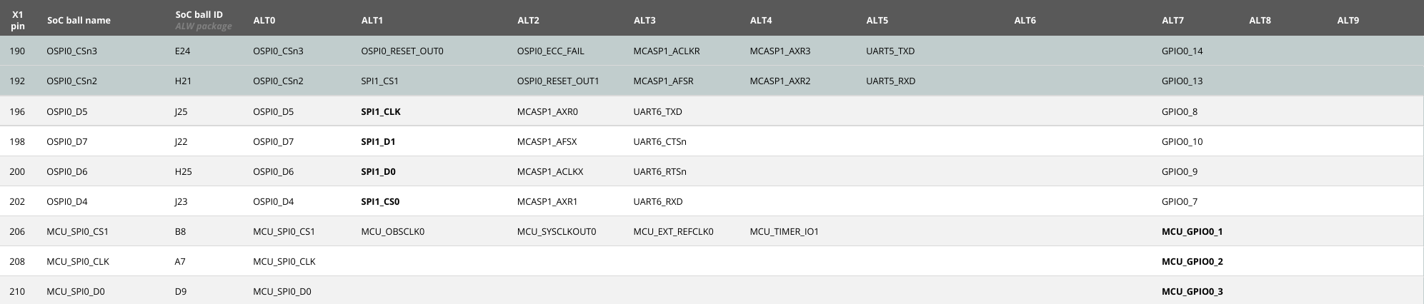
In this article, we will configure pin 202 to use its GPIO function. By default, the pin serves as SPI1_CS0, but it also supports GPIO0_7 as its ALT7 function.
Write an Overlay
Writing a device tree overlay usually involves the following steps:
- Define a target hardware: Specify the hardware (SoC, SoM or peripheral) your overlay will be compatible with.
- Create a pin group: A set of pins configured for specific functions (mux mode, pull-up/pull-down, drive-strength, etc).
- Enable your group: A group by itself does nothing. You need to tell the kernel which peripheral or device should take control of the pin group, in our case, the GPIO controller.
- Avoid Pinmux conflicts: Make sure no other peripheral or device node is using your pin.
The complete overlay is provided below. Throughout this article, we will explore the steps to create it in detail.
Device Tree Overlay to Enable GPIO for Pin 202
/dts-v1/; // Declares the syntax version of the DTS file.
/plugin/; // Indicates that this is a Device Tree Overlay.

// Header file with GPIO macros
#include <dt-bindings/gpio/gpio.h>

// Header file with SoC-specific pinmux macros
#include "k3-pinctrl.h"

/ {
    compatible = "toradex,verdin-am62"; // Set hardware compatibility
};

&main_gpio0 {
	pinctrl-0 = <&pinctrl_ctrl_sleep_moci>,
		    <&pinctrl_gpio_5>,
		    <&pinctrl_gpio_6>,
		    <&pinctrl_gpio_7>,
		    <&pinctrl_gpio_8>,
            <&pinctrl_sodimm_202_gpio>;
};

&main_spi1 {
    status = "disabled";
};

&main_pmx0 {
    pinctrl_sodimm_202_gpio: sodimm_202_gpio_grp {
        pinctrl-single,pins = <
            AM62X_IOPAD(0x001c, PIN_INPUT, 7) /* (J23) OSPI0_D4.GPIO0_7 */ /* SODIMM 202 */
        >;
    };
};
Define the Target Hardware
A device tree overlay starts with the following headers:
/dts-v1/; // Declares the syntax version of the DTS file.
/plugin/; // Indicates that this is a Device Tree Overlay.
The first property that goes after the headers is the compatible one. It specifies all pieces of hardware compatible with your overlay. It follows the pattern "manufacturer,model".
/ {
    compatible = "toradex,verdin-am62";
};
The compatible property specifies all pieces of hardware that are compatible with your overlay. It defines to which drivers your configurations will be applied to. If more than one value is set for the compatible property, the operating system will try to locate the specified drivers in the order that they are writen. For more information on the compatible syntax, check out the Device Tree Specification.
Create a Function Multiplexing Group
Each Toradex module family has a set of Always Compatible interfaces, which are always enabled by default when using our unmodified BSPs. For writing your own custom pinctrl group, a reliable approach is:
- Locate a
pinctrlgroup that enables an Always Compatible instance of your desired interface. - Create a similar device tree group that enables the same type of interface for your specific pin.
For example, according to the Verdin Family Specification, the GPIO_1 signal is Always Compatible. That means, when using our BSPs, you will always find an enabled group for GPIO_1 in the device tree of all Verdin modules. Besides that, from the Verdin AM62 Datasheet, the GPIO_1 pin has the SoC ball name MCU_SPI0_CS1. This means you can find a pin configuration by searching for both pin function (GPIO_1) and ball name MCU_SPI0_CS1 in your SoM's device tree files.
In the case of the Verdin AM62, the GPIO_1 configuration group can be found in the linux/arch/arm64/boot/dts/ti/k3-am62-verdin.dtsi file, as shown below:
&mcu_pmx0 {
    ...
	/* Verdin GPIO_1 */
	pinctrl_gpio_1: mcu-gpio0-1-default-pins {
		pinctrl-single,pins = <
			AM62X_MCU_IOPAD(0x0004, PIN_INPUT, 7) /* (B8) MCU_SPI0_CS1.MCU_GPIO0_1 */ /* SODIMM 206 */
		>;
	};
    ...
};
The syntax shown here is specific to the Verdin AM62 SoM. You will need to refer to your specific board's file. For more information, see our Pinmuxing Guide.
You can use the GPIO_1 group as a reference to create a configuration group for your desired pin. The example below shows a custom function multiplexing group.
&main_pmx0 {
    pinctrl_sodimm_202_gpio: sodimm_202_gpio_grp {
        pinctrl-single,pins = <
            AM62X_IOPAD(0x001c, PIN_INPUT, 7) /* (J23) OSPI0_D4.GPIO0_7 */ /* SODIMM 202 */
        >;
    };
};
Here is a breakdown of the above snippet:
- &main_pmx0: Represents the main pin controller. This is where function multiplexing groups are defined.
- pinctrl_sodimm_202_gpio: The label for the pin group node. This is a custom name you assign, and is used to refer to the group elsewhere in the device tree. This is the label we will assign to the GPIO controller.
- sodimm_202_gpio_grp: The node name of the pin group. Also a custom name, which can appear in kernel debug messages. It is not used elsewhere in the device tree.
- pinctrl-single,pins: The property that contains the actual pin configuration values. This must be set to an array of values, usually generated from SoC-specific macros.
- AM62X_IOPAD(0x001c, PIN_INPUT, 7): An SoC-specific macro that encodes the physical register offset (
0x001c), configuration flag (PIN_INPUT) and the pin function (7).- 0x001c: The offset of the physical address that controls the pin's multiplexing and configuration.
- PIN_INPUT: A macro that configures the pin as input.
- 7: Sets the pin to use the
ALT7function, in our exampleGPIO_1, as noted in Choose a GPIO Pin to Enable.
To find the physical address of the configuration register for your specific pin, search for the pin's SoC ball name in the AM62 reference manual. In this example, the pin is 202, with SoC ball name OSPI0_D4.
The register that configures OSPI0_D4 is PADCFG_CTRL0_CFG0_PADCONFIG7, with the address 0xF401c. To use the macro, you need to use the offset of the pin relative to the first pad configuration register (which is at 0xF4000). Thus, in this case, the relative address is 0x001c.
Activate the Group
The procedure to activate your group consists of the following:
- Find the device tree node where your interface's groups are enabled.
- Add your group to the list of groups to be activated.
A group by itself does nothing. You need to tell the kernel which peripheral or device should take control of the pin group. Devices will appear in the device tree as nodes. The set of groups each device controls is defined by the pinctrl-0 property.
In this example, we will add a new group of pins to the GPIO controller, which is represented by the main_gpio0 node. In our case, we will:
- Find the
main_gpio0pin groups in k3-am62-verdin-dahlia.dtsi, a device tree file that contains definitions for the carrier board. - Add the group to the
pinctrl-0property in our overlay.
Look in device tree files for nodes of the device you want to use. The names of these files usually include the name of the SoC and carrier board. For example, for a Colibri iMX8X with an Aster carrier board, you will find the group of pins for the GPIO controller in the imx8x-colibri-aster.dtsi file.
The snippet below shows the main_gpio0 node in k3-am62-verdin-dahlia.dtsi:
&main_gpio0 {
	pinctrl-names = "default";
	pinctrl-0 = <&pinctrl_ctrl_sleep_moci>,
		    <&pinctrl_gpio_5>,
		    <&pinctrl_gpio_6>,
		    <&pinctrl_gpio_7>,
		    <&pinctrl_gpio_8>;
};
In the k3-am62-verdin-dahlia.dtsi file, there is a mcu_gpio0 node with some pins assigned to it. This device configures the GPIO pins from the Cortex-M4 microcontroller. Since we want to control pin 202 with the main processor (Linux side), we will not change mcu_gpio0. Always refer to your specific datasheet to understand pin assignments and behavior.
Here is a breakdown of the properties used in this example:
- pinctrl-names: A list of names to be assigned to the
pinctrlproperty. Entry 0 of this list will be assigned topinctrl-0, entry 1 topinctrl-1, and so on. - pinctrl-0: An array of phandles, each referencing a pin control group that the device will use. Each phandle corresponds to a group defined elsewhere in the device tree.
In our case, we are adding <&pinctrl_sodimm_202_gpio> to the set of groups that will be managed by the GPIO controller for its default state. In our overlay, the main_gpio0 node will look as follows:
&main_gpio0 {
    pinctrl-0 = <&pinctrl_ctrl_sleep_moci>,
            <&pinctrl_gpio_5>,
            <&pinctrl_gpio_6>,
	    <&pinctrl_gpio_7>,
            <&pinctrl_gpio_8>,
            <&pinctrl_sodimm_202_gpio>;
};
Note that overlays do not alter properties they do not specify. That is why we did not include the pinctrl-names property. However, you must include the GPIO groups that were originally referenced in pinctrl-0, since your overlay will overwrite the pinctrl-0 property completely.
Resolve Pin Conflicts
With the GPIO function enabled for your pin, you must disable any previous interface that used the same pin to avoid resource conflicts. According to the Function Multiplexing table, pin 202's original function was SPI1_CS0. To release the pin from the SPI controller, we will disable the corresponding SPI device node in our overlay as follows:
&main_spi1 {
    status = "disabled";
};
Include Required Headers
For the device tree overlay to compile, you need to include any header files that provide macros or symbolic constants you use in your overlay, like AM62X_IOPAD and GPIO_ACTIVE_HIGH.
// Header file with GPIO macros
#include <dt-bindings/gpio/gpio.h>

// Header file with SoC-specific pinmux macros
#include "k3-pinctrl.h"
Build and Deploy the Overlay
This section provides the steps for applying device tree overlays to Torizon OS images, specifically with TorizonCore Builder. This tool facilitates the process and discards the need for Yocto. For alternative methods, see Compile the Device Tree Overlay.
-
Download a Toradex Easy Installer image of Torizon OS.
-
Create a YAML configuration file. This file specifies the target images and overlays to be applied. To enable the overlay we created previously for a GPIO pin, our configuration file will look as follows:
tcbuild.yamlinput:
# Target image
easy-installer:
local: torizon-docker-verdin-am62-Tezi_7.2.0+build.13
customization:
device-tree:
include-dirs:
# Folder that contains common kernel header files like gpio.h
- linux/include
# Folder that contains SoC-specific header files for TI, like k3-pinctrl.h
- linux/arch/arm64/boot/dts/ti/
# Top-level device tree source file that will be used.
# This file's name includes the name of the target SoC and carrier board.
# Note that we are including a a device tree source file (dts) and not a dtsi file.
custom: linux/arch/arm64/boot/dts/ti/k3-am625-verdin-wifi-dahlia.dts
add:
# Overlay to be applied
- /device-trees/overlays/gpio-verdin-am62-overlay.dts
output:
easy-installer:
# Output folder
local: custom-torizon-docker-verdin-am62
# Image name
name: Torizon OS - GPIO pin muxingDo not forget to add the folders for the header files you have added to your overlay (like
k3-pinctrl.handgpio.h) toinclude-dirs. The location of SoC-specific headers will vary:- TI-based SoMs:
linux/arch/arm64/boot/dts/ti/. - NXP-based SoMs:
arch/arm64/boot/dts/freescale.
- TI-based SoMs:
-
Ensure your file structure is correct. For example, our
tcbuild.yamlwould required the following:├── linux
├── device-trees
│ └── overlays
│ └── gpio-verdin-am62-overlay.dts
├── tcbuild.yaml
└── torizon-docker-verdin-am62-Tezi_7.2.0+build.13 -
Ensure you have sourced the TorizonCore Builder setup script.
Test the Overlay
Check if the overlay was successfully applied.
To test the GPIO pin, you can use command-line tools provided by the libgpiod library. On Torizon OS, you can use a prebuilt container provided by Toradex that already contains the required dependencies.
For a pin in GPIO controller 2, line 7, run the following command to drive the pin to the high state:
## gpioset 2 7=1
For more information on finding the controller and line of your particular GPIO pin, proceed as follows:
How to find out the controller and line of your pin
To test the GPIO pin you enabled in your overlay, you will need two pieces of information to pass to the gpioset command:
- The GPIO line offset: The index within the GPIO controller. It can be obtained from the SoM datasheet. For the Verdin AM62 pin 202, the GPIO alternate function is
GPIO0_7, so its line offset is 7. - The GPIO controller: On Linux, it will be represented as a
gpiochipNdevice, whereNrepresents each GPIO controller.
For dedicated GPIO pins, this information is easily obtained by using the gpioinfo or gpiofind commands, as instructed in Test GPIO Pins from a Container. However, when you modify a non-dedicated pin to enable its GPIO alternate function, your changes will not be reflected in the output of these commands.
To find the gpiochipN device that corresponds to your GPIO controller, follow these steps:
-
Find the physical address of the GPIO controller you used to activate your group. This information can be obtained from either:
- The SoC reference manual: Look for the GPIO memory map for your GPIO controller. For example, GPIO0 is at the address
0x0000600000on the Verdin AM62. - The device tree: Look for the controller definition in the device tree. It will contain the address in the
regproperty. For the Verdin AM62, this information can be found in k3-am62-main.dtsi, the SoC-specific device tree include file, specifically in themain_gpio0node.
- The SoC reference manual: Look for the GPIO memory map for your GPIO controller. For example, GPIO0 is at the address
-
The kernel creates character devices for each GPIO controller. On your SoM, check which GPIO controller file has the physical address you found. You can list the GPIO devices as shown below:
## ls -l /sys/dev/char/ | grep gpioOn the Verdin AM62, the command returns the following:
lrwxrwxrwx 1 root root 0 Apr  9 16:32 13:65 -> ../../devices/platform/gpio-keys/input/input1/event1
lrwxrwxrwx 1 root root 0 Apr  9 16:32 254:0 -> ../../devices/platform/bus@f0000/20010000.i2c/i2c-1/1-0021/gpiochip0
lrwxrwxrwx 1 root root 0 Apr  9 16:32 254:1 -> ../../devices/platform/bus@f0000/bus@f0000:bus@4000000/4201000.gpio/gpiochip1
lrwxrwxrwx 1 root root 0 Apr  9 16:32 254:2 -> ../../devices/platform/bus@f0000/600000.gpio/gpiochip2
lrwxrwxrwx 1 root root 0 Apr  9 16:32 254:3 -> ../../devices/platform/bus@f0000/601000.gpio/gpiochip3
From the file
/sys/devices/platform/bus@f0000/600000.gpio/gpiochip2, we know that our controller is at thegpiochip2controller.
Troubleshooting
Issues may arise when designing device tree overlays. Although the device tree compiler should catch any syntax errors and point out their source, an overlay can still cause unexpected behavior when applied to the system.
-
If your device does not boot:
- Check if you disabled the previously used function of your pin.
- Connect to your board via serial and try rebooting your system to view the boot log information.
-
If your device boots, but your desired functionality does not work:
- Make sure your overlay is applied
- Read the kernel messages using
dmesgfor debug information.
-
In case your device boots, but certain interfaces stop working (e.g., Ethernet):
- Check if you disabled the previously used function of your pin.
- Review your overlay and check if you are overwriting any properties incorrectly. For example, when adding a new group to the
pinctrlsettings, remember to keep all original groups.
Additional Example: LED Blink
This section presents a second example demonstrating how to configure a pin for blinking an LED using the LED driver, specifically targeting the Verdin iMX8M Mini. This example aims to solidify the concepts explained in previous sections, as well as provide an overlay for a different SoM. Here, we will reinforce the most important differences and concepts. For complete details on each step of the configuration, refer to the beginning of this article.
The complete overlay is shown below, with a few key points highlighted for a deeper understanding of the overlay:
View led-blink-verdin-imx8mm-overlay.dts
/dts-v1/;
/plugin/;

#include <dt-bindings/gpio/gpio.h>
#include <dt-bindings/leds/common.h>
#include "imx8mm-pinfunc.h"

/ {
	compatible = "toradex,verdin-imx8mm";
};

&pwm1 {
	status = "disabled";
};

&pwm2 {
	status = "disabled";
};

&{/} {
	leds {
		compatible = "gpio-leds";

		pinctrl-names = "default";
		pinctrl-0 = <&pinctrl_my_led>;

		myled_sodimm_15 {
			label = "my_led_sodimm_15";
			gpios = <&gpio5 4 GPIO_ACTIVE_HIGH>;
			linux,default-trigger = "heartbeat";
			default-state = "on";
		};

		myled_sodimm_19 {
			label = "my_led_sodimm_19";
			gpios = <&gpio1 1 GPIO_ACTIVE_HIGH>;
			linux,default-trigger = "heartbeat";
			default-state = "on";
		};
	};
};

&iomuxc {
	/*pinctrl-0 = <&pinctrl_gpio1>, <&pinctrl_gpio2>,
				<&pinctrl_gpio3>, <&pinctrl_gpio4>,
				<&pinctrl_gpio7>, <&pinctrl_gpio8>,
				<&pinctrl_gpio_hog1>, <&pinctrl_gpio_hog2>, <&pinctrl_gpio_hog3>,
				<&pinctrl_pmic_tpm_ena>, <&pinctrl_my_led>;*/
	pinctrl_my_led: myledgrp {
		fsl,pins =
			<MX8MM_IOMUXC_SPDIF_RX_GPIO5_IO4  0x104>; // SODIMM 15 // pull-down enabled and drive strength X2
			<MX8MM_IOMUXC_GPIO1_IO01_GPIO1_IO1 0x104>, // SODIMM 19 // pull-down enabled and drive strength X2
	};
};
- The
leds { compatible }property: Thecompatibleproperty specifies the driver that the OS will look for to match the node's properties. - The
ledsnode configures theleds-gpio.cdriver. For each property's value meanings and specifications, refer to linux/Documentation/devicetree/bindings/leds/leds-gpio.yaml. - Unlike the Verdin AM62, the Verdin iMX8M Mini's pinmuxing groups are defined at the
iomuxcnode instead ofmain_gpio0. See more details on the Verdin iMX8M Mini's pinmuxing syntax at Pinmuxing i.MX 8M Mini/Plus Based Modules. - From the Verdin iMX8M Mini's datasheet, in the Alternate Functions table, the SODIMM 15 and 19 pins have the
PWM1_OUTandPWM2_OUTfunctions by default. Therefore, you need to disable thepwm1andpwm2devices.
To test the overlay, follow the steps below:
- Deploy the overlay to your device.
- Connect a pair of LEDs to the SODIMM 15 and 19 pins. If you are using the Verdin Development Board, you can simply connect a jumper wire from the SODIMM pins to one of the user LEDs (LED21-24).
If your overlay was applied correctly, you should see the LEDs blinking repeatedly, following a "heartbeat" rhythm. The LED devices you created can be found at /sys/class/leds, see Linux Leds Documentation for more information about the LED driver.