First Steps with Resistive Touch Display 7" Parallel
Introduction
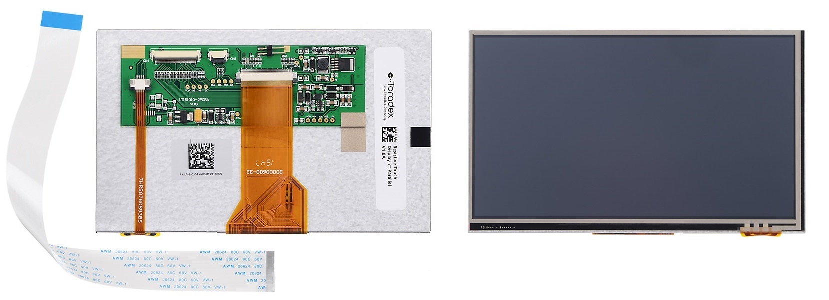
This article provides information on how to start working on the parallel resistive touch display, which includes how to set up the hardware (wiring) and install the necessary drivers for a touch demo.
Getting Started
What I need to order
The Resistive Touch Display 7" Parallel can be ordered with many Toradex computer on modules and carrier boards. See the compatible products.
Where do I order
All the products can be ordered online in the Toradex Webshop.
Cable Connection
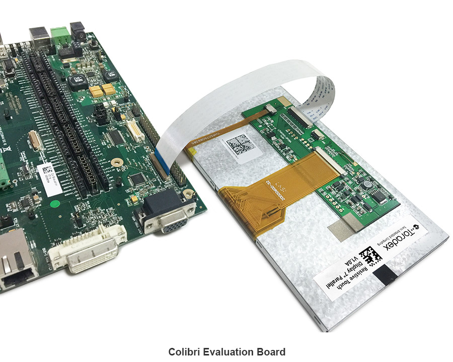
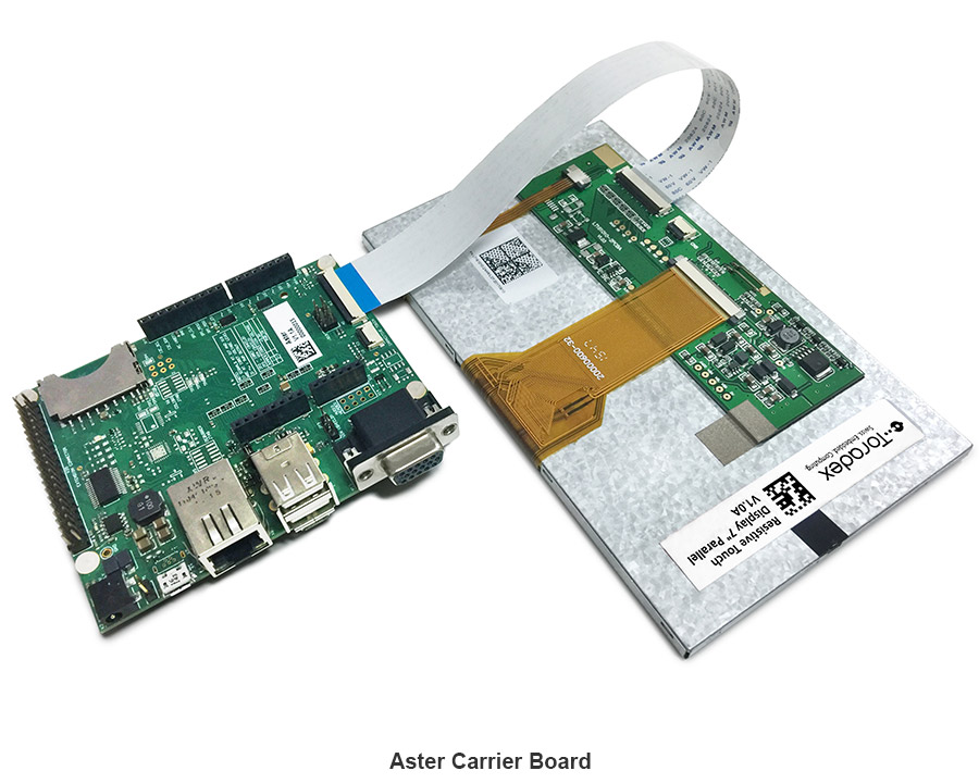
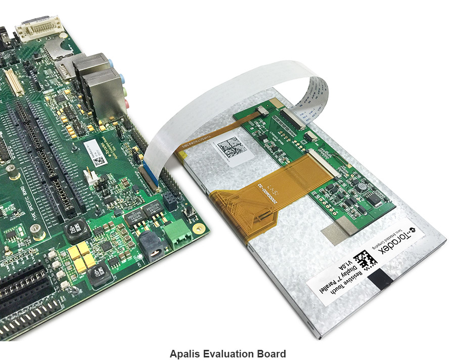
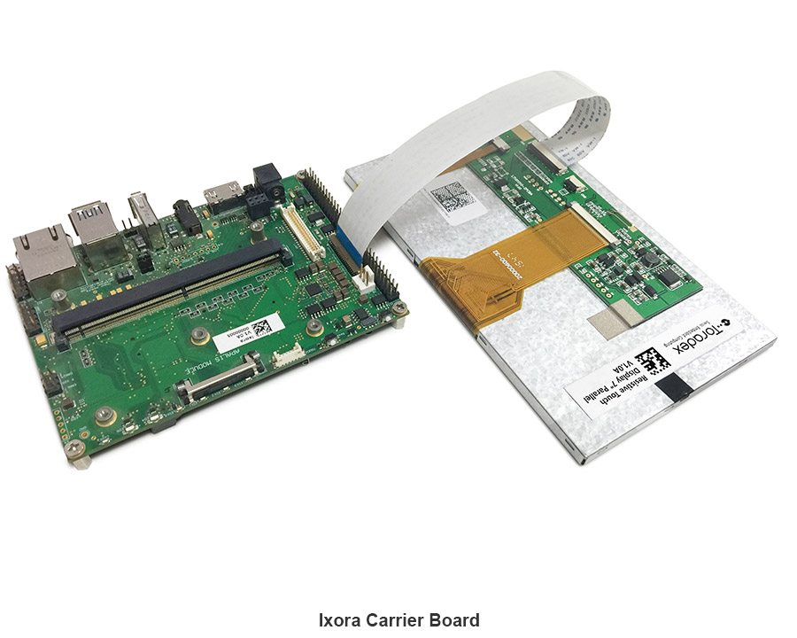
When connecting the display to any of our carrier boards, make sure that pin 1 of the display is connected to pin 1 of the board. Due to the nature of the FFC connectors, it is possible to invert the pinout and possibly damage the display and/or carrier board.
- The connectors available on the display do have contacts on top and bottom side.
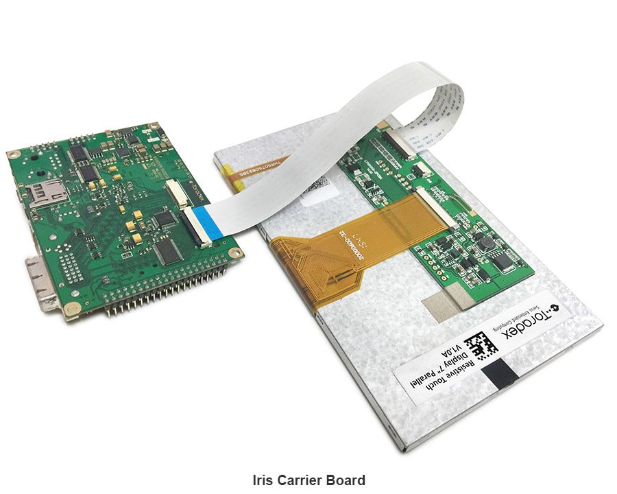
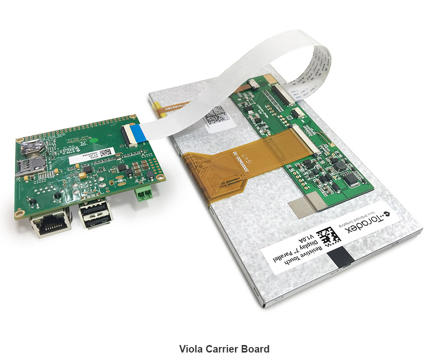
- Our Iris & Viola Carrier Boards also has contacts on top and bottom side of the FFC connector.
- The FFC connectors on the Colibri Evaluation Board, Ixora carrier board & Apalis Evaluation Board has only contacts on the side towards the board edge.
Also, be careful with the brown levers on the connectors. They are very delicate and can easily break.
Please have a look at the pictures below which show how to connect the display with our carrier boards & Evaluation boards:
Installation on Embedded Linux
Torizon OS
On Torizon OS, Toradex deploys pre-compiled and ready-to-use device tree overlays for this display, inherited from the BSP layers. Enabling them for evaluation can be done with a few commands. Learn how to do it on Setting up Displays with Torizon.
Reference Images for Yocto Project
On the Linux BSP, Toradex deploys pre-compiled and ready-to-use device tree overlays for this display. This enables you to evaluate it with few commands and very fast. Learn how to do it on Device Tree Overlays (Linux).
BSP 2.8 - Ångström
To configure the correct display resolution, stop U-Boot by pressing any key while booting and set the vidargs environment variable according to your module as described below. For more information refer to the Display Output, Resolution and Timings article.
Colibri VF50/VF61
setenv fdt_fixup 'fdt addr ${fdt_addr_r} && fdt resize && ${fdt_resolution} && ${fdt_touch}'
setenv fdt_resolution 'fdt set /panel compatible "logic,lt161010-2nhc"'
saveenv
Colibri iMX6
setenv vidargs 'video=mxcfb0:dev=lcd,FusionF07A,if=RGB666 video=mxcfb1:off fbmem=8'
saveenv
Colibri iMX6ULL/iMX7
setenv vidargs 'video=mxsfb:800x480M-16@60,pixclockpol=1'
saveenv
Colibri iMX8X
Unfortunately, Colibri iMX8X does not support vidargs changes, and the configuration should be changed directly in the device tree.
You can see an example with compatible changes here: Device Tree Customization Examples.
Apalis/Colibri T20/T30
setenv vidargs 'video=tegrafb0:pixclockpol:0,800x480-16@60'
saveenv
Apalis iMX6
setenv vidargs 'video=mxcfb0:dev=lcd,FusionF07A,if=RGB24 video=mxcfb1:off video=mxcfb2:off video=mxcfb3:off fbmem=32M'
saveenv
Apalis TK1
The Apalis TK1 does not provide the RGB interface required for the screen to work.
For more advanced use cases, please refer to the article Display Output, Resolution and Timings (Linux).
Adjusting the Brightness
Read the dedicated article Backlight (Linux).
Touch Screen
Resistive touch screen works out-of-the-box in our BSP. To learn more about resistive touch, read the article Resistive Touch Screen (Linux).
Touch Screen Calibration
Read the dedicated articles:
- Touch Screen Calibration (Linux): if you plan to use our BSP Layers and Reference Images for Yocto Project
- Touch Screen Calibration (Torizon): if you plan to use Torizon.
Installation on WinCE
Resolution
-
Download the CAB installer according to the OS you are using:
- [CAB installer for WinCE6 & WEC2007](https://docs.toradex.com/104596-toradexresistivetchslncab-ce6-ce7.zip "Cab installer for 7" parallel RGB resistive touch display_WinCE6_7")
- [CAB installer for WEC2013](https://docs.toradex.com/104597-toradexresistivetchslncab-ce8.zip "Cab installer for 7" parallel RGB resistive touch display_WinCE8")
-
Connect the display with the provided FFC cable to the Carrier Board or Evaluation Board paying attention to the pin numbering on the display and on the carrier board.
-
Copy the downloaded CAB installer to the Flash memory of the module or any of the memory device connected to the module like SD Card, USB Memory Stick, CF Card etc.
-
Run the installer by double clicking on it. If you do not have a working display, use the Remote Display tool.
-
Click "OK" on the popup window.
-
Adjust the splash screen settings. This is particularly important for newer displays because they need proper resolution and timings at boot. You can find more information about this here. You can even set the proper resolution and timing parameters of RGB display through registry settings:
- Don't forget to save the registry after editing.
- For more information about these registry keys see: Display Driver Registry Settings
Brightness
If you connect the display with our standard Carrier boards you may experience that the display does not show to maximum brightness. To get the maximum brightness you need to set the back-light PWM_A signal to output 0.
| Module | Signal Name | SODIMM Pin/MXM pin | GPIO Pin | Display Pin |
|---|---|---|---|---|
| Colibri PXA270 | PWM_A | 59 | 12 | 6(LEDCTRL) |
| Colibri PXA300 | PWM_A | 59 | 20 | 6(LEDCTRL) |
| Colibri PXA310 | PWM_A | 59 | 20 | 6(LEDCTRL) |
| Colibri PXA320 | PWM_A | 59 | 14 | 6(LEDCTRL) |
| Colibri T20 | PWM_A | 59 | B4 Note1 | 6 (LEDCTRL) |
| Colibri T30 | PWM_A | 59 | B4 Note1 | 6 (LEDCTRL) |
| Colibri VF50 | PWM_A | 59 | PTC7 | 6 (LEDCTRL) |
| Colibri VF61 | PWM_A | 59 | PTC7 | 6 (LEDCTRL) |
Note1: SODIMM pin 59 on Colibri T20 and T30 has two CPU signals assigned (multiplexed) L5 and B4. Make sure you set B4 to output 0 and L5 to input.
Whereas, for Apalis T30 on a standard Apalis carrier board use GPIO C.00.
| Module | Signal Name | MXM Pin | GPIO Pin | Display Pin |
|---|---|---|---|---|
| Apalis T30 | BKL1_PWM | 239 | C.00 | 6 (LEDCTRL) |
For a test you can use the GPIOConfig Tool.
- For the translation of alphanumeric GPIO identifiers to numeric ones see: GPIO Alphanumeric to GPIO Numeric Assignment.
Touch Screen Calibration on Win CE
The parallel RGB display also features resistive touch screen interface on the same FFC.
To calibrate the touchscreen see: Touch Screen Calibration.
To make the calibration permanent, you need to save the registry.