How to use CAN library
this is a legacy library and thus not supported by Toradex anymore. We recommend that you use the new libraries for all Toradex modules. Please see the Toradex CE Libraries and Code Samples for up-to-date information.
CAN (controller area network) is a multi-master broadcast serial bus standard communication. CAN is a message-based protocol, designed specifically for automotive to allow communication between devices within a vehicle without a host computer.
Use Cases:
- Automotive
- Aerospace
- Industrial automation
- Medical equipment
- and much more.
Setting up CAN test on Colibri/Apalis Evaluation Board
Take two Colibri Evaluation Board V3.1 or newer or Apalis Evaluation Board 1.0 or newer and connect using CAN bus at CAN connector (X2 on Colibri EVB, X32 on Apalis EVB).
To make CAN bus connection
- Take two different colored wires (for example Red and Green) of length around 40 cm and twist them.
- Terminate both ends of a twisted pair with 120 Ohm resistor.
- Solder Red and Green wire to pin 2 and pin 7 of Female D-Type connectors respectively in both sides.
- Connect Female D-Type CAN connector (X2) to respective D-Type CAN connector on (X2) Colibri Evaluation boards or (X32) Apalis Evaluation Board
Precautions
Colibri Tegra and PXA
- On Evaluation Board V3.1, SPI Lines SODIMM_73 (CAN_INT), SODIMM_86 (SSP_FRM), SODIMM_88 (SSP_SCLK), SODIMM_90 (SSP_RXD), SODIMM_92 (SSP_TXD) are directly connected with MCP2515 CAN controller. So you must ensure that jumpers are fixed and these lines are not used for other purposes.
- To use the CAN-Lib on a PXA310 you have to connect X12 pin 41 with X12 pin 31 on the Colibri Evaluation Board 3.0.
- You must run receive at first device then before starting the transmit in another device.
Colibri i.MX6, i.MX6 and Vybrid
You can use the external MCP2515 controller, as described for Colibri Tegra and PXA above, or use the internal CAN controller. In this case you'll need to connect the pins of the CAN controller you plan to use (all the modules have 2 controllers) to the CAN connector. To do that you need to remove the jumpers from the jumpered connectors (X8 or X11, depending on the pins you need to use, please check the module datasheet for detailed information) and connect the module output pins (X9 or X10 connector) to the CAN transceiver via connector X38. Remember to also remove jumpers JP4 and JP5 to disconnect the external controller from CAN bus.
Apalis modules
CAN interface is part of the standard Apalis pinout. It is implemented via an external controller (Tegra) or directly by the SOC (iMX6). The Apalis Evaluation board provides 2 can connectors (X32A and X32B) that can be used without any additional hardware configuration.
Demo application (old version of libraries, PXA and Tegra only)
- Setup the development environment for Colibri module on Windows CE by following this guide.
- Download the free CAN Demo code and library from here.
- Build and Deploy project on Colibri device.
- This program uses ISR (CANLibMCP2515ISRDll.dll), copy it into Windows directory of Colibri device.
- Repeat the step 3 and 4 for second Colibri device.
- Run the application on both devices and follow the steps in the console window thereafter.
Output
After executing the .exe file you will see the following window.
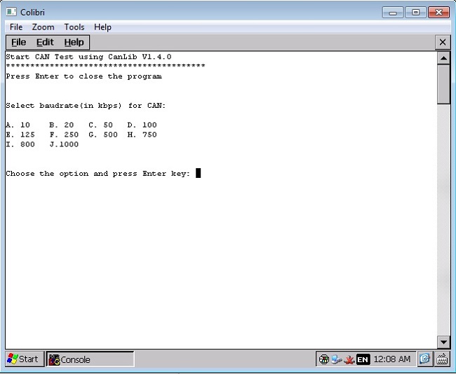
After selecting Baudrate Press 'R' for Receive.
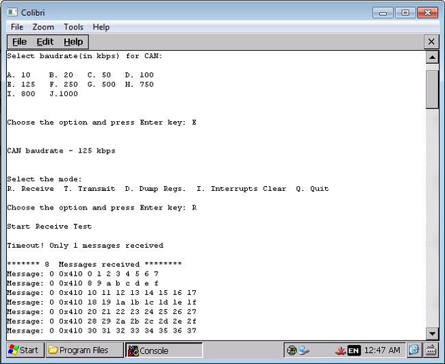
Enter "T" will transmit Demo message.

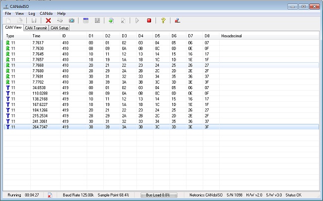
Output of CAN analyser showing Received and Transmit message.For more information on CANdo analyser click here
CAN support in the new libraries (Tegra, Vybrid, i.MX6, i.MX7)
You can find our new libraries here and the downloadable package contains both the CAN libraries and a sample application to start testing CAN connectivity.